mostly printed camera slider – part 3

Has been tested intensively now. Works ok, with a little practice. I guess I can´t expect more from a printed design due to the weight shift with 500 g class DSLMs. Nevertheless thats enough to do some close slides for products etc.

See it slide here:

There might be some documentation necessary before releasing it on thingiverse as the mechanism needs to be adjusted correctly.

Designing and Building a Dual-head 3D Printer

I had the opportunity to try out at least 5 different printers. All of them had sifgnificant backdraws like missing heatbed, price and noise. They all did there job anyway and my Fabrikator is working pretty much „fire and forget“ all the time. Nevertheless I´m tempted to create my own printer just for the sake of adding it to my collection of valuable experiences.

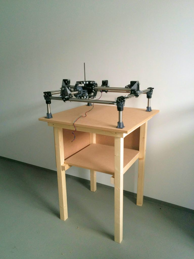
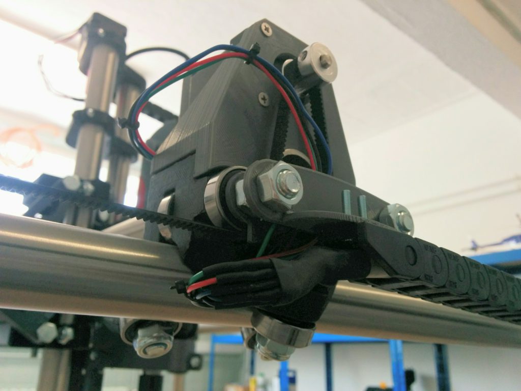
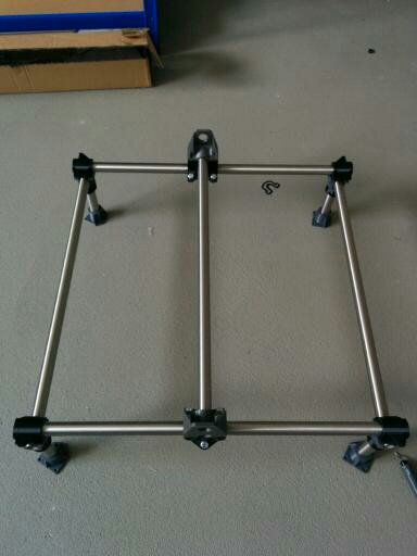
I came up with T-Bot first iteration closely related to prusa´s I3 framewise. I didn´t liked the Z leadscrews standing out that much and too far away from the linear slides so the second version focused on making this a little more aerodynamic.

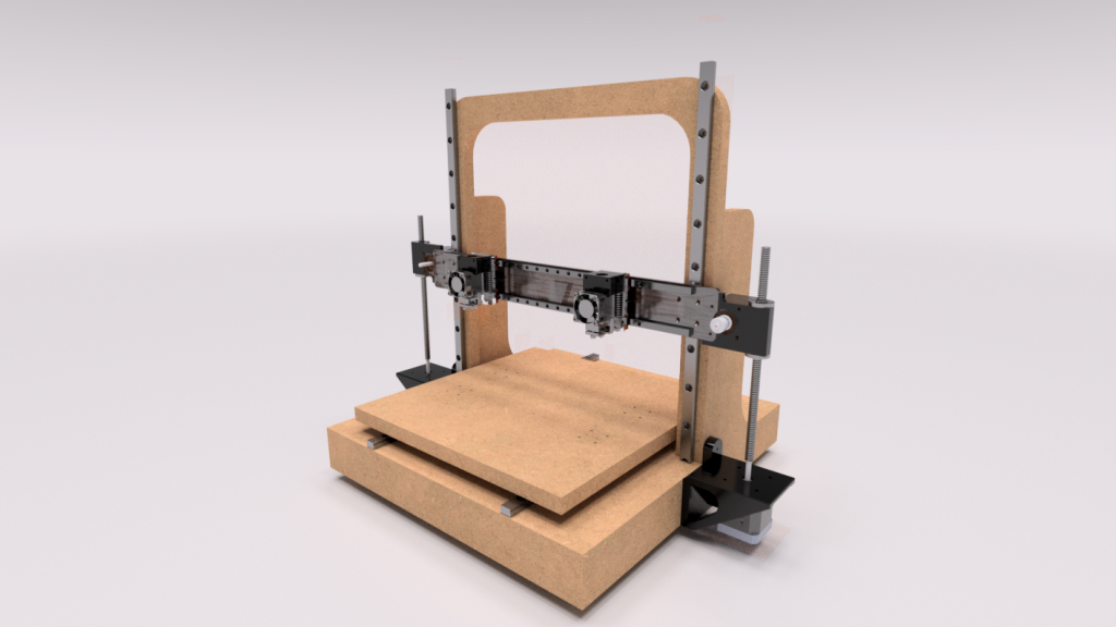
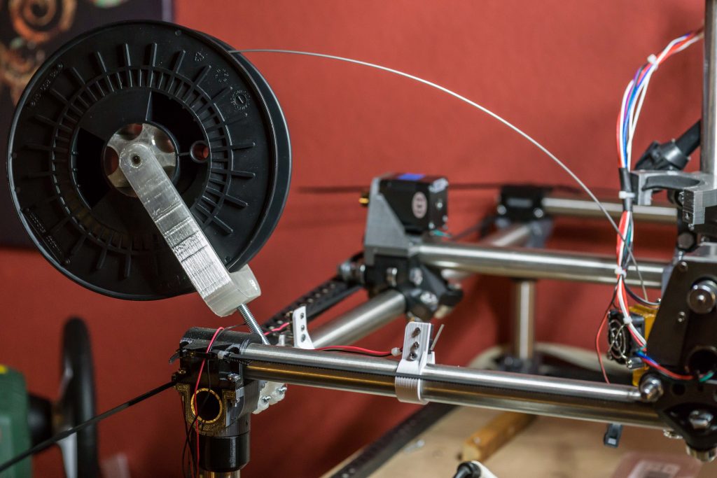
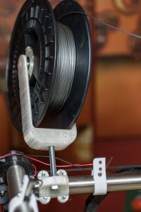
I am aiming for a precise as possible head and bed positioning mechanics with dual extrusion the bowden way. I have good experience with bowden so I don´t see any significant disadvantages at the moment.

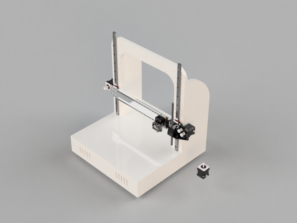
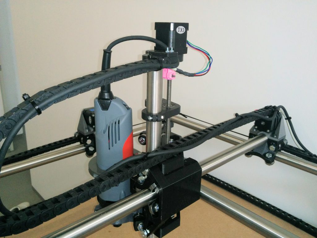
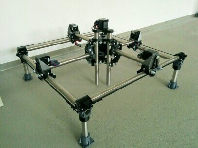
The second version with the new z and x mechanics.

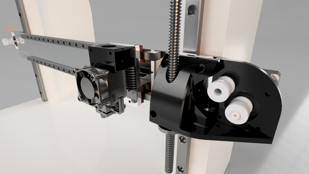
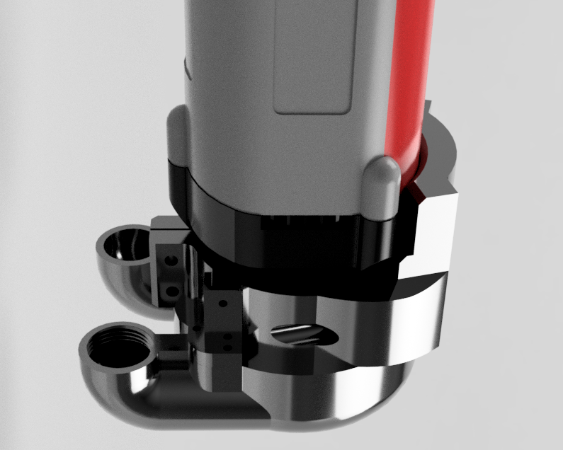
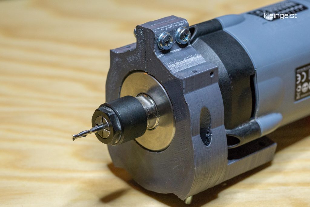
There are E3D V6 mounted on the gantry at the moment but it should be stable enough for light milling operations.

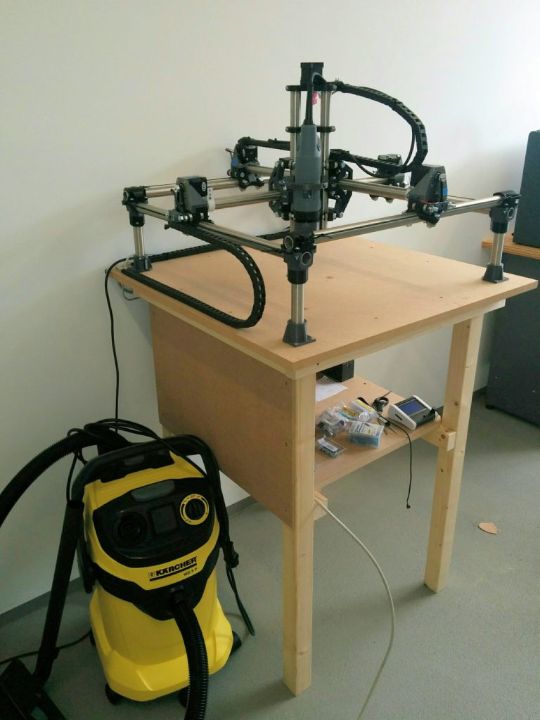
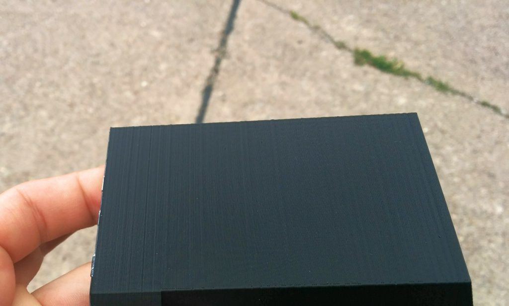
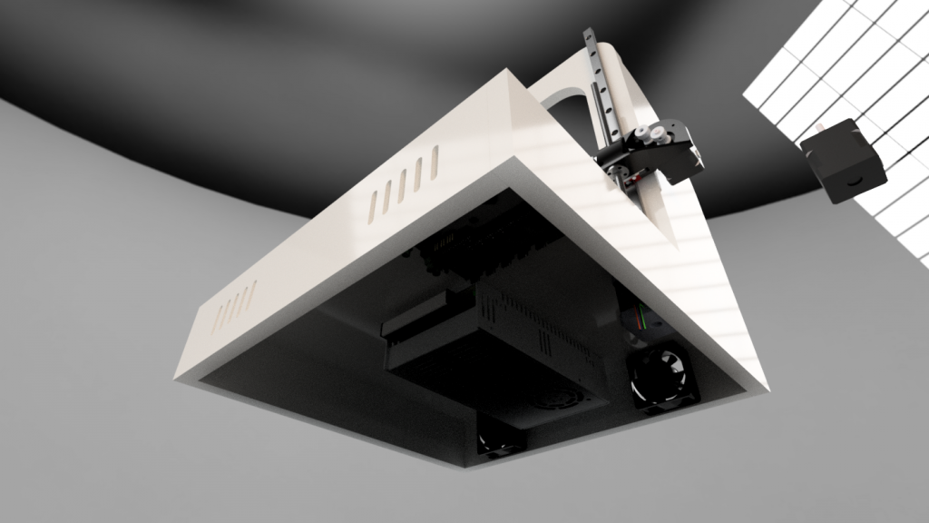
The frame is designed with 16mm MDF in mind but I probably change to a different material (not OSB). Thats why I have to redesign most of the frame parts as the new material is somewhat thinner.

I already have most of the electronic components in mind. The first prototype might be powered by components I have laying around but the finished version is meant to be state of the art 🙂

Watching Thomas Sanladerer´s channel really helped me out making decisions at some points in the design process so thank you for your effort in making great videos, if you ever read this.


MPCNC – New KRESS FME800q tool-holder with dust shoe assembly

First render of the new tool holder with dust shoe, connected at the bottom. The goal was to stiffen the spindle for aluminum milling and the transition to a more comfortable suction system as I don´t like standing next to it for an hour.

The clamp itself has already been printed and the vaccuum attachment is on its way. I will see how this turns out and if I need some kind of brush to bridge the gap to the workpiece or if the pure airflow is strong enough to keep the chips and dust under control. The spindle is closer to the gantry and sits firmly clamped by two M4 screws with washers and nylocks.

Sorry for the bad print quality, it is printed in PETG and I didn´t dialed in the parameters carefully as this is a plain mechanical part with no optical ambitions 😛

Those are my preparations for the nex aluminum milling test runs and the upcoming bigger project that might cause lots of dust.

MPCNC filament spool holder

My Hobbyking Fabrikator prints just nice but there are times when the build volume is just not big enough. So why not use the capabilitys of the MPCNC for that? I used the MK8 Extruder and mount from Ryan and designed a compact spool holder that uses leftover parts I had from the CNC build. In my case those are two M8 metric screws with a length of 70mm, a nut and two 608 bearings. Combined it looked like this:Spool holder postion

MPCNC spool holder

The clamp for 25mm tubes is fastened with four M3 *16 and nylock nuts. It can be rotated to aim at the printhead. For now it is available for center holes of 53mm and a width of 53 mm spools.

It can be downloaded here: http://www.thingiverse.com/thing:2002909


Building a MPCNC part 3- cutting

In order to find a suitable endmill I had to understand the principles involved first. That led me to feeds and speeds. The difficult part was to determine the limits of my cnc. I already had a look on that topic when I chose my Spindle. It has a minimum RPM of 10000 and a maimum of 29000 RPM so I decided to go for a 2 flute endmill with a diameter of 3 mm from cnc-plus.de. More on the calculation later..

After testing the gcode and finding out if the steps/mm of the steppers are dialed in correctly I used a simple ruler to check. Josef Prusas stepcalculator gave me 160 steps/mm and that resulted in the correct distance of movement with my 20 tooth pulleys. As I couldn´t  set the parameters from the graphic display I had to reflash the Marlin firmware.

I used a M8 threaded rod like suggested in the original plans. It is not meant for machine operations and so It loves to do what it is designed for. It binds pretty often, resetting the z axis position and making sudden, unexpected deep cuts as shown in the video below. It is the straightest rod I could find and it is well greased but it was necessary to lower the acceleration and speed. I only had this one piece of hardwood and I wanted this to suceed. I´m trying to get the speed back up again because the milling took ages (1h15min) because of the adaptive clearing and the many retractions of the tool head.

The 3D printed rigid couplers didn´t worked to well for me so I ordered a jaw coupler also from http://cnc-plus.de to make it more reliable.

In conclusion : I liked the results of the cuts and they were somehow thrilling. The accidentially super deep cuts showed that I can go much deeper than 3mm in one pass with hardwood. The method used here was also a test for the ultimate goal for cutting alumium sheet and composites.


Building a MPCNC part2

So I spent some hours on weekends to advance further into my CNC adventure and it came out pretty satisfying.

img_20160916_170838

Simple CNC stand

Before wiring everything together, I saw the need of a good platform, so I don´t have to wire it again once I found a suitable platform. It took around 6 hours to build this from standard „Baumarkt“ supplys.

img_20160922_1536352

I guided all six cables per axis down to the controller board. I wasn´t sure If I might change the controller board and thus the method of actuation later. I used 8 pole shielded datacable from Lapp Kabel. I added some endstops after I ordered the cables so I have to wire them seperetaly.

img_20160922_153656

Z Axis with Kress FME800 and a pink solid coupler

The M8 threaded rod wasn´t straight and wobbles badly so the Z Axis binds from time to time when running. I´m going to change that for a trapezoidal screw soon. The printed rigid coupler also starts to crack. I need a better part for this too.

Everything else works good so far. The Stepper drivers are getting a little hot but I got a small fan as a leftover from my Fabrikator mod that will be mounted on a 3d printed case or similar.

img_20160922_153710

Complete setup with vacuum and cablework done

Getting endmills and doing the first cut is the next target,


Building a MPCNC

I started building a MPCNC router after I stumbled upon vicious1s design on thingiverse. I really liked the design and couldn´t resist to start ordering the electrical parts and the required conduit.

MPCNC Rollers

MPCNC Rollers and first stepper mount

I took pretty long to get all the parts printed correctly, as my printer was modded right before the prints and it wasn´t to clear how it will perform. The MPCNC prints served well as a long time test of the modifications

Almost complete

Almost complete

I quickly assembled the parts I had so far to see what it gonna look like

1471636054102

First test fitting

All fitted very well, the conduit is stainless steel whitch came pre cutted. I needed to source some screws I had to use M4 for the most parts as M3,5 as suggest by Ryan was harder to find. After I got them it didn´t took long to get the majority of the CNC parts together.

1471701993534

Assembled stage 1,5

Great moment for me, as I coulnd´t stop thinking about anything else than finishing this nice little machine up. I made it 70 x 70 cm resulting in a build volume of around 40 x 40cm x 10 cm.

Next steps cover the electronics, base plate and the spindle. I will go for a Kress FME 800.


Turnigy Fabrikator E3D – mod

When Hobbyking lowered the price for the Turnigy Fabrikator I couldn´t resist any longer and decided to take the risk of ordering. The build up was pretty straight forward and I had it up in like 8 hours. I did a little calibration and and added a rapsberry pi with octoprint to the setup in conjunction with cura. Everything worked pretty well, especially the leveling of the print bed which was a one time setup thing. Printig was pretty much fire and forget and overhangs came out pretty well. However…

The print quality was ok but I never was too impressed with the layer alignment so I decided to do a little upgrade on the extruder with an original E3D hotend and a bowden mod.

I used a modification already available on http://www.thingiverse.com/thing:1534340 by Manuel Stassar. I recycled the old Extruder mount to use it as bowden extruder to keep it simple (lazieness). The prints seem to be much better now but I have to test it more.

IMG_20160809_173142~2

Much better layers