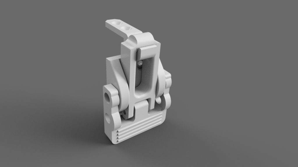
Einfacher Verschluß, ursprünglich für meine CNC-Einhausung gedacht. Vorteil ist das heranziehen der Tür an die Dichtlippe der Isolierung und die gute Vibrationsdämpfung.
STEP included!
Einfacher Verschluß, ursprünglich für meine CNC-Einhausung gedacht. Vorteil ist das heranziehen der Tür an die Dichtlippe der Isolierung und die gute Vibrationsdämpfung.
STEP included!
Ursprünglich lag der Fokus auf der Konstruktion von Drohnensystemen. Für die kompromissfreie Herstellung war mein Fabrikator aber einfach schlichtweg zu klein und konnte fast nur PLA drucken. Ich hab viel Zeit damit verbracht zu überlegen was ich mir für einen Drucker anschaffen sollte. Ich pendelte zwischen Ultimaker 2, Prusa Mk2 und Ryans MP3DP. Ich wollte aber zwingend ein Design das ich selbst relativ schnell anpassen kann, daher lag es nahe alles selbst entworfen zu haben um auch jeden Winkel des Aufbaus zu kennen und gleichzeitig tiefer in die Materie einzutauchen, da ich ja bisher das meiste Wissen bei Copter und Modellbau bzw Industrieelektronik erworben hatte.
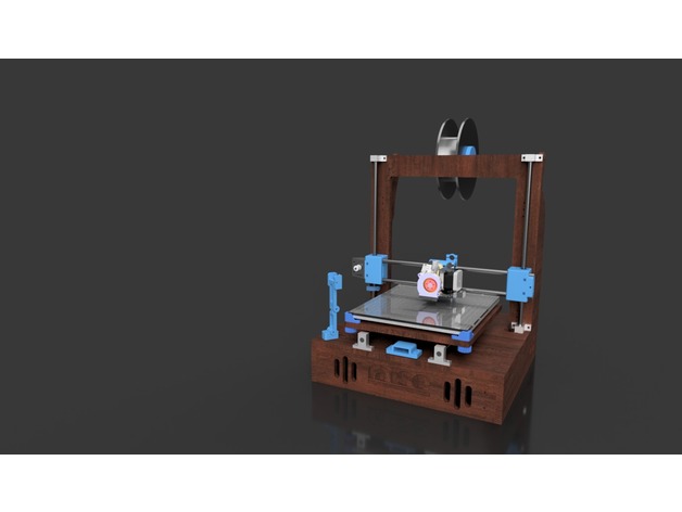
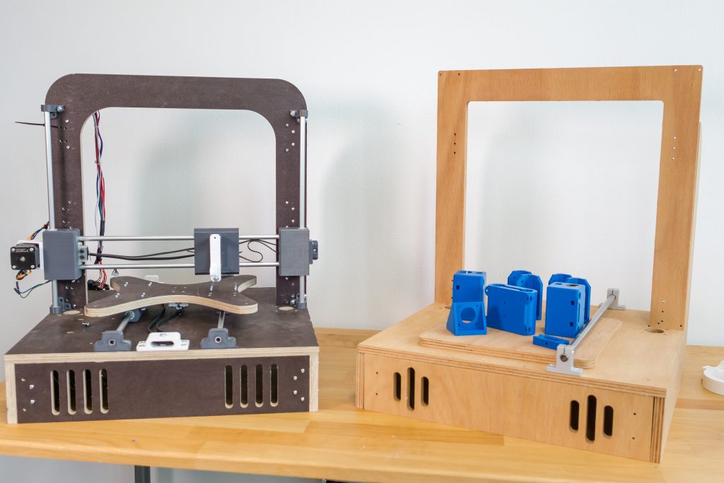
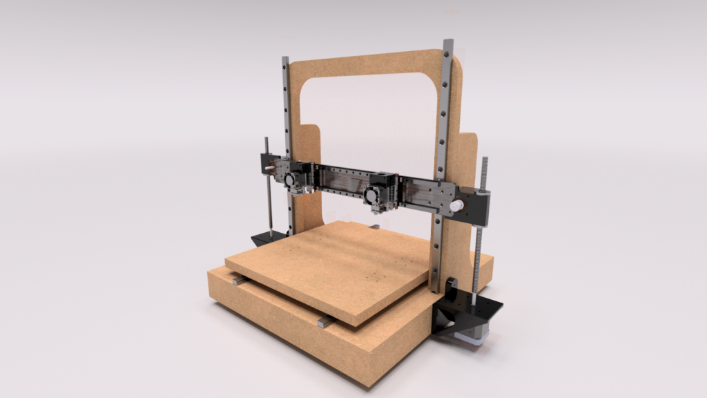
Der erste Prototyp aus Siebdruckplatten vom örtlichen Baumarkt war schnell gebaut und hatte hohle 8mm „Linearwellen“ aus Aluminum. Das war natürlich die aller unterste Grenze und trotz der recht krummen Leitspindeln sahen die Drucke relativ gut aus. Es gab deutlich Artefakte in Z aber für ein schnelles Konzept ganz erträglich.
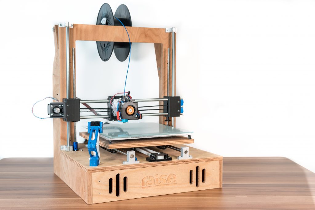
Aus den gewonnen Erfahrungen und einem besseren Gefühl für das Design erwuchs dann der d³. Es war zur Abwechslung mal sehr entspannend nicht auf jedes Gramm wie im Copterbau achten zu müssen. Die jetzt eingesetzten 10mm Stahlführungen, die leicht zu beschaffen sind zeigten dann auch eine wesentlich höhere Genauigkeit und ich war wesentlich zufriedener mit dem gesamten Design. Als schwierig stellte sich jedoch das finden von größeren Ebenen Betten heraus. Dieses musste dann auch noch kompensiert werden da der Holzrahmen sich gern mal um wenige ,05 Millimeter bewegte. Durch den einbau des Servo ausfahrbaren Z-Tasters konnte das nun auch behoben werden, nachdem einiges an gefiddel mit dem Minitronics, an dem ich die Pins falsch abgezählt hatte, glücklich zu Ende ging.
Das ganze sollte auf kleineren Fräsen herstellbar sein als Außenmaß kam daher für meine kleine MPCNC 400 x 400mm in Frage daher auch die etwas untypische Bettform. Ich fand es wichtig alles so einfach wie möglich herstellen zu können und externe Dienstleister zu vermeiden. Zwar musste ich letztendlich doch extern fertigen lassen da meine Fräse nicht ganz rechteckig war, wodurch sich auch der etwas höhere Preis erklärt aber hey ich konnte immerhin die zwei Protoypen unkompliziert direkt fertigen. Derzeit wird das externe fertigen von http://teil-q.de übernommen die nebenbei auch sehr schönes Modellbauzubehör anbietet.
Ja was soll ich sagen. Ich bin wirklich sehr zufrieden mit dem Design. Sicher ist da auch etwas Subjektivität und Stolz dabei aber die Drucke laufen wirklich gut. Ich hatte bisher 5 verschiedene Drucker im professionellen Einsatz und alle waren sie irgendwo gut bis auf ein Modell das nicht zum zuverlässigen Drucken zu bringen war trotz des guten Druckbilds. Ich wollte einfach die gesamte Baufläche voll stellen können und nach Beendigung meine, oft auch mal komplizierten, Teile ohne Artifakte vom Bett nehmen und verwenden können. Dort bin ich nun endlich angekommen auch dank des tollen E3D- Titan das nach dem beheben der Kugellagerprobleme mit Ballistol sehr schöne Ergebnisse abliefert.
Damit ich weiter entwickeln kann, vom Teemaker bis zum Y6 Hexakopter, bin ich natürlich auch auf ein Einkommen angewiesen daher hab ich den kleinen schon erwähnten Shop eröffnet über den ich einen kleinen Teil der Entwicklungskosten decken möchte. Daher würde ich mich freuen wenn einige das Gesamtprojekt unterstützen möchten und nebenher die Bauzeit verkürzen.
https://raise-uav.com/projekte/raise-three-d/
Das ganze ist so Open-Source wie möglich gehalten. Mit Freecad bin ich einfach zu langsam obwohl ich damit eingestiegen bin, daher musste ich auf das für Maker und Bastler kostenlose Fusion 360 umschwenken. Es gibt dennoch ein STEP Modell für weitere Kompatibilität.
Da er nun schon längere Zeit am Käfig rüttelt, konnte ich nichts anderes tun als zumindest die beta Version von meiner prusa I3 Interpretation in die Wildnis zu entlassen.
Meinen erhabensten Dank an folgende Vorreiter und Supporter:
https://www.thingiverse.com/thing:2655471
Dokumentation etc. auf https://raise-uav.com/projekte/raise-three-d/ oder im Git repo (latest) hier
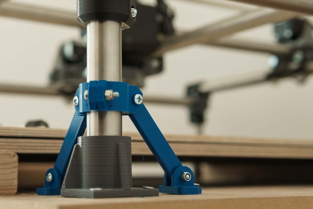
My MPCNC showed some significant flex on the four main feet. I wanted to solve this quickly with small amounts of material and without additional hardware, except screws.
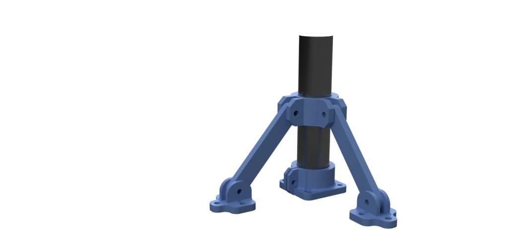
It might look kind of funny and when you already modified your corners in some other way or got them low, the aren´t necessary I guess. If you still got most of the original parts, this little gem will help 🙂
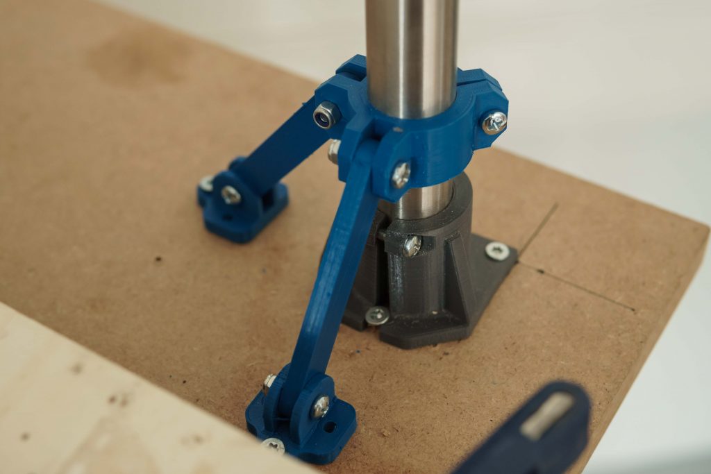
Bring the two feet in place, screw them down and the clamp will bring up the tension on the struts.
Files Include modified feet.
Surprise! I had a common chip clearance problem. I considered this as a cause from the beginning and also got some tips from the vicious1..com forum. I milled two complete sets of 3D-printer frames without problems so I couldn´t believe that this was really the cause.
I drew a test pattern and managed to get it right with an additional ,5mm helical drilling movement. That seems enough for the chips to clear the hole.
I don´t have that much time to get into those issues but the parts didn´t came out perfectly rectangular yet. I tried to manually adjust the stepper position before powering it up but thats still not enough to get the precision I need. I´m using all of the available travel so I´m getting quite a big error in the end.
I need to readjust the frame and the feet as well.
I currently got some problems with drilling holes again. It seems there is something odd in the Z- axis. I didn´t assembled it carefully enough. I suppose that the spindle isn´t lowered in a straight line, instead it is tilted on the way down pushing the endmill into the material sideways and ripping a hole into my plywood.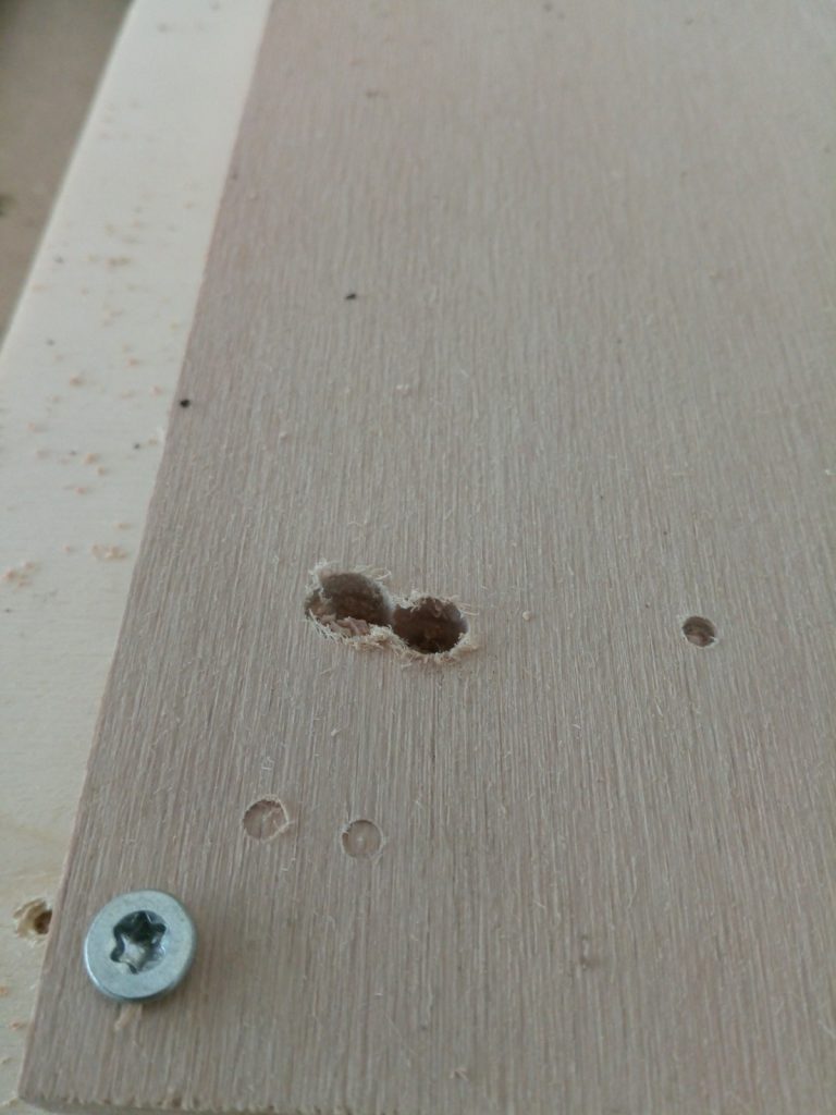
I´m using this as a reason to reprint the tool- and steppermount.
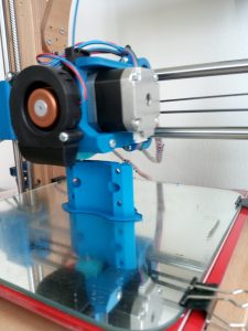
When I originally build the MPCNC I had no drillpress and the terrible idea to tap a M4 thread into the stainless. This is a bad idea as it clearly makes the alignment of the screws in the tool mount to the conduit almost impossible.
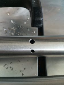
I redrilled the holes and I am now using the original path with the nut traps inside the conduit. Along with the adjustment of the leadscrew this hopefully improves the precision and rigidity of my z-axis.
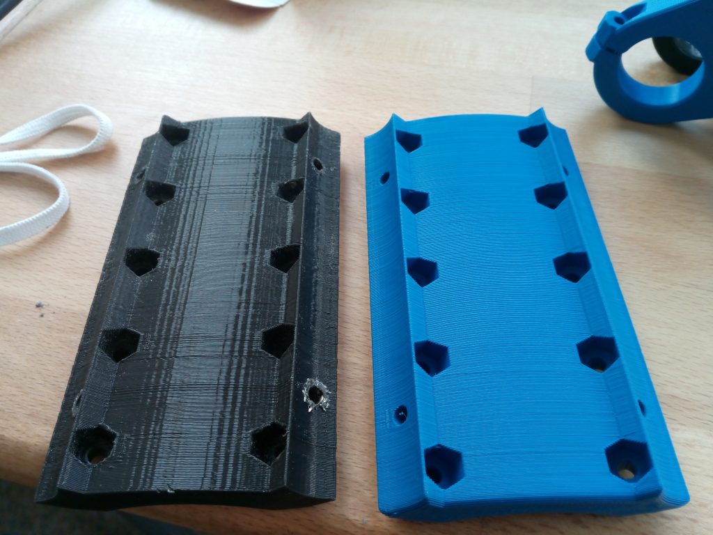
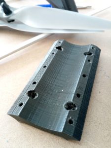
Finished toolmount replacement. The one on the left was printed with an pre R17 BCN3D Sigma and the right one printed with my DIY printer.
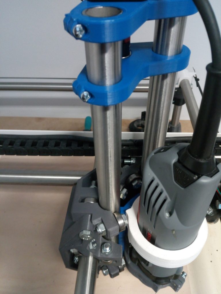 Now everything is assembled again. The tubes are now „perfectly“ straight and parallel. I used a glass plate to verify the alignment.
I did a short test run and I had the same result as before. A nice circular vibration and a not very pretty drill hole. I´m using a diamond cut endmill at the moment and went successfully through two sets of printer frames. I´ve been told in ryans formum (viscious1.com) that diamond cut bits are everything but ideal to dive 12mm into beech plywood. They are very robust so they were the only ones that survived when it came to an error. They are compressing the shavings within the hole and that leads to more and more pressure hence the heat rises and the endmill escapes in the circular movement.
In the past I ordered a endmill from sorotec which broke after some drilling operations. That left me confused what the error might be. I also tried a shorter endmill originally for aluminum which transported the shavings quiete nicely but was too short.
I ordered new endmills again and hopefully all the possible errors caused by the machine are gone and I get my drill patterns and contours out of one endmill.
Wish me luck!
I founded a little company called raise-UAV. The main advantage is the increased time for my projects and that was totally necessary when I look at my roadmap. 🙂
It is primarily focused on the development of open drone systems manufactured with 3D printing technology.
The printer and the mini ghost I´ve started here will be hosted on the company side to keep things easier. Other things not drone and printer related will be posted here on the kleingeist blog in detail. Next bigger projects are a printed and easy to build kajak and an „earth rover“ for research purposes.
There will also be a shop on raise-uav.com where you can buy kits and ready made articles to keep me funded for further development.
I also began a video series picturing the builds and other useful content with its first episode right here
Cheers 🙂
I had the opportunity to try out at least 5 different printers. All of them had sifgnificant backdraws like missing heatbed, price and noise. They all did there job anyway and my Fabrikator is working pretty much „fire and forget“ all the time. Nevertheless I´m tempted to create my own printer just for the sake of adding it to my collection of valuable experiences.
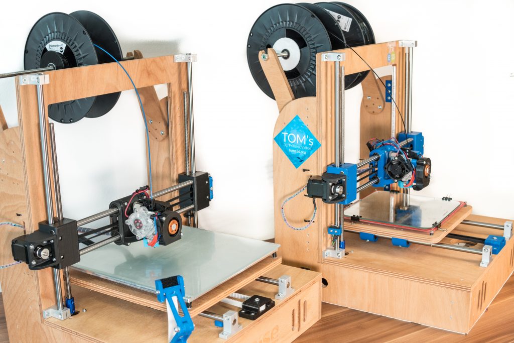
I came up with T-Bot first iteration closely related to prusa´s I3 framewise. I didn´t liked the Z leadscrews standing out that much and too far away from the linear slides so the second version focused on making this a little more aerodynamic.
I am aiming for a precise as possible head and bed positioning mechanics with dual extrusion the bowden way. I have good experience with bowden so I don´t see any significant disadvantages at the moment.
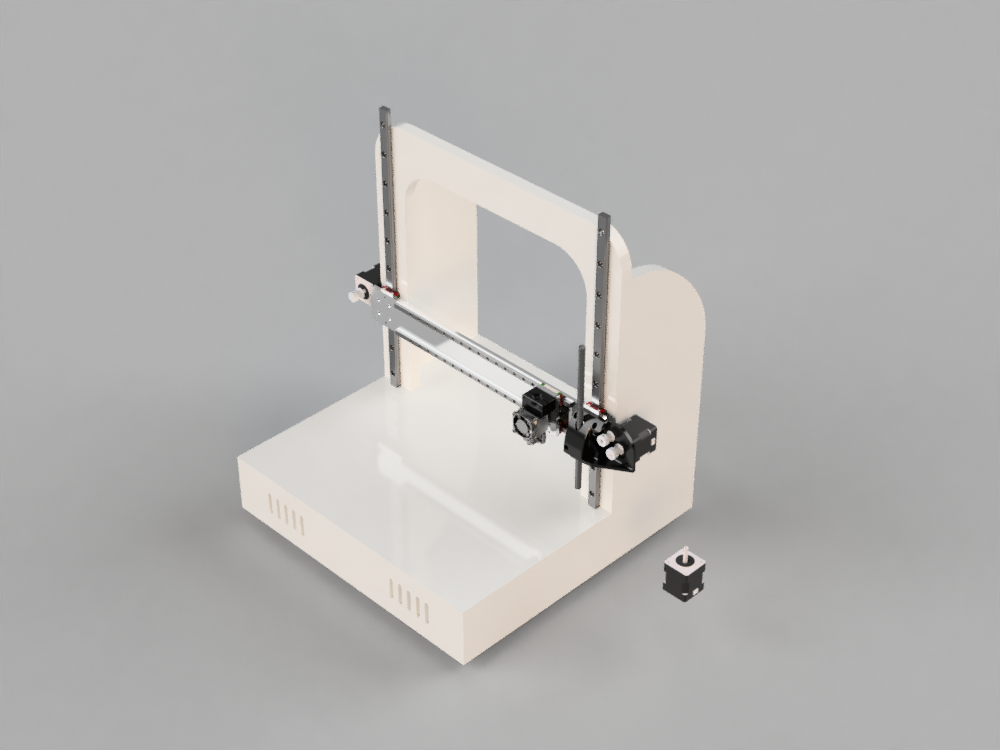
The second version with the new z and x mechanics.
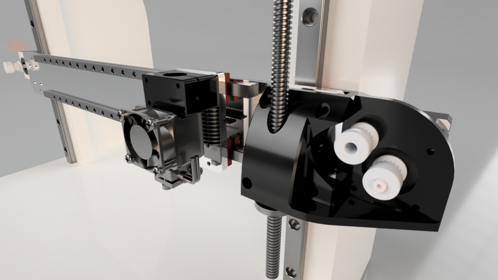
There are E3D V6 mounted on the gantry at the moment but it should be stable enough for light milling operations.
The frame is designed with 16mm MDF in mind but I probably change to a different material (not OSB). Thats why I have to redesign most of the frame parts as the new material is somewhat thinner.
I already have most of the electronic components in mind. The first prototype might be powered by components I have laying around but the finished version is meant to be state of the art 🙂
Watching Thomas Sanladerer´s channel really helped me out making decisions at some points in the design process so thank you for your effort in making great videos, if you ever read this.
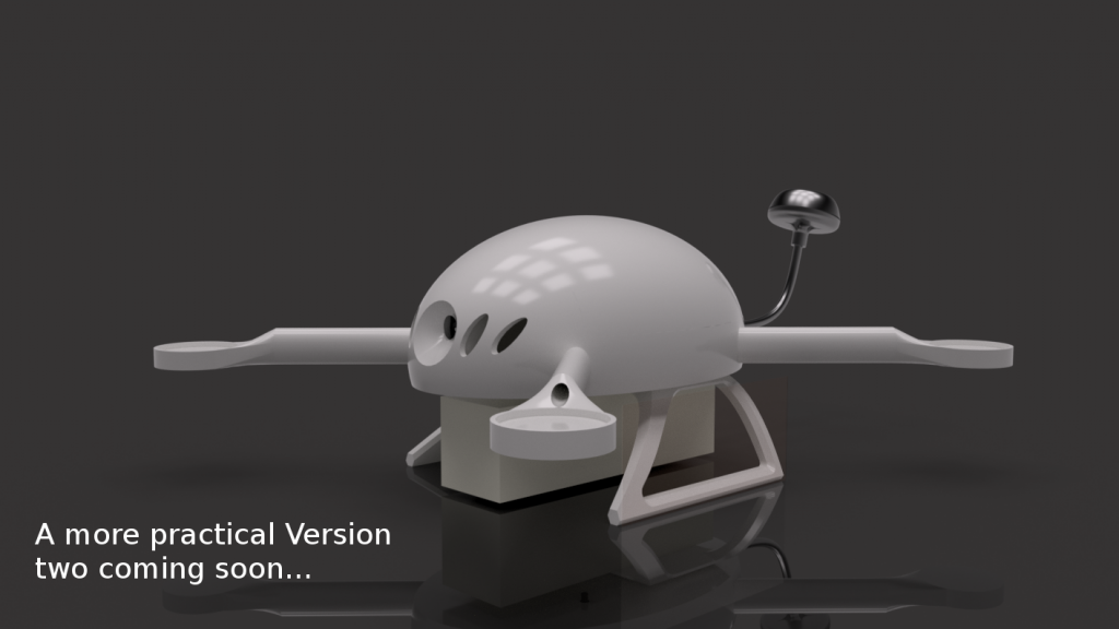
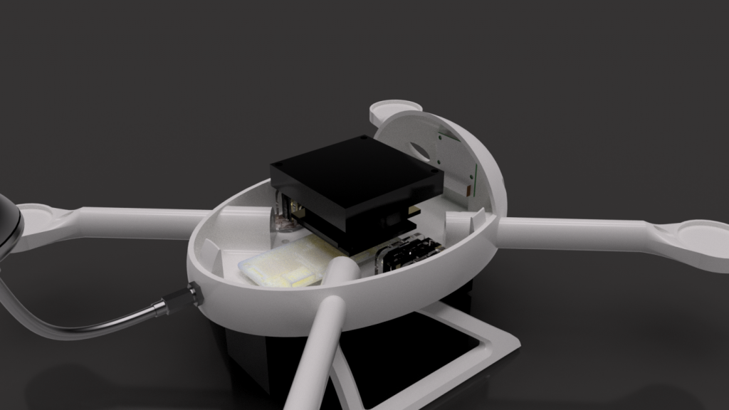
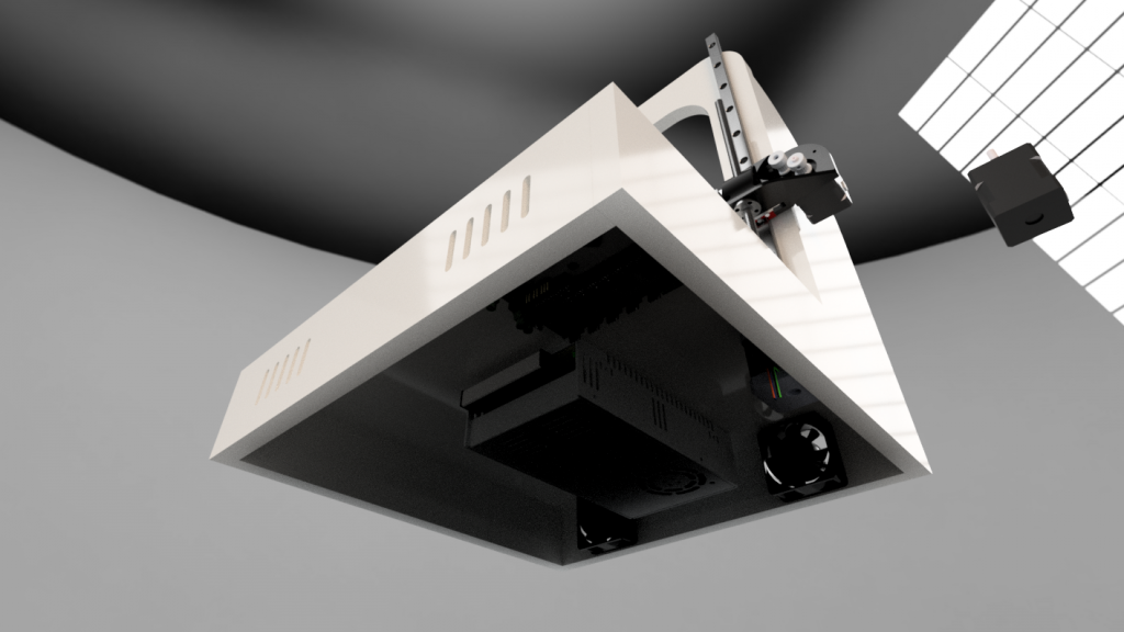
I took another iteration to make it move like it should. As you can see, in comparison to the previous entry, the case and the mechanics have been modified. The belt system used is a bit more complicated than I initially thought and I couldn´t get it to perform „super smooth“ like its contestants.It is best suited for actioncams as you can see in the picture below. I tried a DSLM and it works somehow but it flexes under the load generating a somewhat unstraight path.
I think it´s okay anyway, taking the money spend into account versus performance. At least it was a good exercise. In the video below are some cam transitions made with it so get the idea of the achievable smoothnes. It´s more like basecap than edelkrone 😛
This project is currently in long term testing and refinement stage.
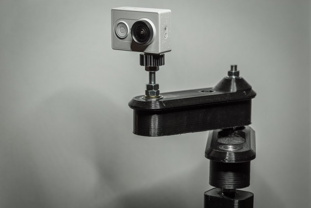
Inspired and a bit fascinated by the glide arm style camera sliders I decided to build my own version of it.
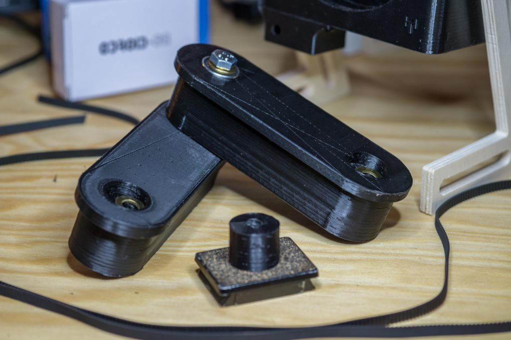
The parts are all standard you got laying around either from a MPCNC build or if you like modifying or building 3D printers. Anythin else can be sourced from your local hardware store or other sources.
 It is not working yet as I´m wating on some hardware parts that are announced for arrival next week. After that it will be tested in various conditions and then maybe released into the wild 🙂
Parts list:
-soon-