MPCNC – „Cornerdefender“

My MPCNC showed some significant flex on the four main feet. I wanted to solve this quickly with small amounts of material and without additional hardware, except screws.

It might look kind of funny and when you already modified your corners in some other way or got them low, the aren´t necessary I guess. If you still got most of the original parts, this little gem will help 🙂

Bring the two feet in place, screw them down and the clamp will bring up the tension on the struts.

Files Include modified feet.

https://www.thingiverse.com/thing:2548942

MPCNC- solved drilling issue

Surprise! I had a common chip clearance problem. I considered this as a cause from the beginning and also got some tips from the vicious1..com forum. I milled two complete sets of 3D-printer frames without problems so I couldn´t  believe that this was really the cause.

I drew a test pattern and managed to get it right with an additional ,5mm helical drilling movement. That seems enough for the chips to clear the hole.

I don´t have that much time to get into those issues but the parts didn´t came out perfectly rectangular yet. I tried to manually adjust the stepper position before powering it up but thats still not enough to get the precision I need. I´m using all of the available travel so I´m getting quite a big error in the end.

I need to readjust the frame and the feet as well.

MPCNC- maintenance and rework of the z-axis

I currently got some problems with drilling holes again. It seems there is something odd in the Z- axis. I didn´t assembled it carefully enough. I suppose that the spindle isn´t lowered in a straight line, instead it is tilted on the way down pushing the endmill into the material sideways and ripping a hole into my plywood.

I´m using this as a reason to reprint the tool- and steppermount.

When I originally build the MPCNC I had no drillpress and  the terrible idea to tap a M4 thread into the stainless. This is a bad idea as it clearly makes the alignment of the screws in the tool mount to the conduit almost impossible.

I redrilled the holes and I am now using the original path with the nut traps inside the conduit. Along with the adjustment of the leadscrew this hopefully improves the precision and rigidity of my z-axis.

Finished toolmount replacement. The one on the left was printed with an pre R17 BCN3D Sigma and the right one printed with my DIY printer.

Now everything is assembled again. The tubes are now „perfectly“ straight and parallel. I used a glass plate to verify the alignment.

I did a short test run and I had the same result as before. A nice circular vibration and a not very pretty drill hole. I´m using a diamond cut endmill at the moment and went successfully through two sets of printer frames. I´ve been told in ryans formum (viscious1.com) that diamond cut bits are everything but ideal to dive 12mm into beech plywood. They are very robust so they were the only ones that survived when it came to an error. They are compressing the shavings within the hole and that leads to more and more pressure hence the heat rises and the endmill escapes in the circular movement.

In the past I ordered a endmill from sorotec which broke after some drilling operations. That left me confused what the error might be. I also tried a shorter endmill originally for aluminum which transported the shavings quiete nicely but was too short.

I ordered new endmills again and hopefully all the possible errors caused by the machine are gone and I get my drill patterns and contours out of one endmill.

Wish me luck!


MPCNC – finished dust shoe system

Inspired by one of my readers I had a look  at the dust shoe for the Kress again. I redesigned it completely and got rid of the additional tubes and clamps. I thought that it would be a good idea to have a highly flexible part between vaccum and CNC. If I had ordered the 20mm silicon tubes it may have worked as well but reducing parts is allways priority.

So in the end we got a pretty classic dust shoe here. It doesn´t have a brush at the bottom as it seems to work pretty good at the moment and I really like to see the endmill. However I included three holes at the bottom for a later brush design.

It works pretty good with lighter materials but GFK, aluminum or similar are not fully sucked up.

It has been printed in 0,3mm draft quality for testing purposes.

It has been released on thingiverse here http://www.thingiverse.com/thing:2119491

Now also available in my shop here

MPCNC – New KRESS FME800q tool-holder with dust shoe assembly

First render of the new tool holder with dust shoe, connected at the bottom. The goal was to stiffen the spindle for aluminum milling and the transition to a more comfortable suction system as I don´t like standing next to it for an hour.

The clamp itself has already been printed and the vaccuum attachment is on its way. I will see how this turns out and if I need some kind of brush to bridge the gap to the workpiece or if the pure airflow is strong enough to keep the chips and dust under control. The spindle is closer to the gantry and sits firmly clamped by two M4 screws with washers and nylocks.

Sorry for the bad print quality, it is printed in PETG and I didn´t dialed in the parameters carefully as this is a plain mechanical part with no optical ambitions 😛

Those are my preparations for the nex aluminum milling test runs and the upcoming bigger project that might cause lots of dust.

MPCNC – Long-term testing and material decisions

1. Long-Term observations on the XYZ part

I found a small crack in the XYZ gantry today. This is the second time that I´ve seen this. I milled some aluminum as you may know and I had a mild crash when setting up the endstops but I thought I was fast enough switching it off before it took damage. I printed some parts in the meantime and re tightened the XYZ assembly.

This is obviously a weak spot in the construction, at least if you over tighten the gantry. This is hard to measure as it will break sometime after tightening even without use. It was printed with the suggested high infill and outer wall settings but with a line infill instead of grid. That also could have influenced the partstrength.

The first time it happened on the upper XYZ part. I printed the replacement part out of PETG. It seems much stronger and surprisingly it is not bending the tiniest amount. I expected PETG to be tougher but more flexible but in direct comparison with the PLA part underneath in a tightened state on the machine this is way stiffer. (grey)

2. Conclusion

I´m reprinting the bottom XYZ part with PETG.
Thomas Sanladerer tested the same PETG in his filaween series and he confirmed the toughness of the material. The flexibility of PETG can be neglected in my opinion.

MPCNC filament spool holder

My Hobbyking Fabrikator prints just nice but there are times when the build volume is just not big enough. So why not use the capabilitys of the MPCNC for that? I used the MK8 Extruder and mount from Ryan and designed a compact spool holder that uses leftover parts I had from the CNC build. In my case those are two M8 metric screws with a length of 70mm, a nut and two 608 bearings. Combined it looked like this:Spool holder postion

MPCNC spool holder

The clamp for 25mm tubes is fastened with four M3 *16 and nylock nuts. It can be rotated to aim at the printhead. For now it is available for center holes of 53mm and a width of 53 mm spools.

It can be downloaded here: http://www.thingiverse.com/thing:2002909


Desklamp „century“ part 2

I did finish the first „century“ lamp just in time for christmas. The base is very close to the CAD design, thanks to the excellent work of a friend and his lathe. The apple wood turned quite dark, alltough I used a clear finish. The lampshade printed from natural PLA gave it an almost glass like appearance. I´m currently refitting the MPCNC with an extruder so I may be able to print the more complex lampshades soon as my Hobbyking Fabrikator is just a bit too small for the task. I´m pretty happy with the result so far. Now I have to dive deeper into aluminum milling to get it a little more stiff.


MPCNC – Quickstart in DE

1. Gedanken zur Materialbeschaffung

Grundsätzlich ist es von Vorteil die gedruckten Teile sowie Fräser und Zubehör bei Ryan (Vicious1.com) zu bestellen. In die Konstruktion und den Service fließen viele Arbeitsstunden. Man sollte zumindest eine Spende in Erwägung ziehen um das Projekt zu unterstützen.
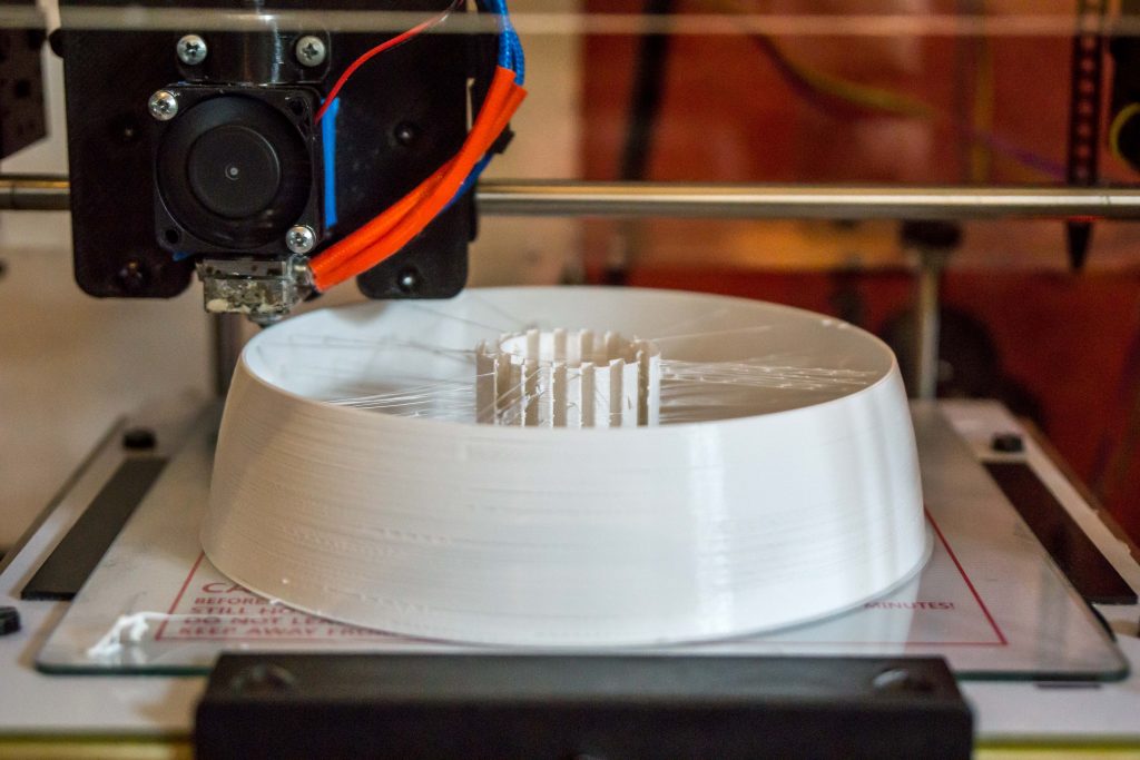
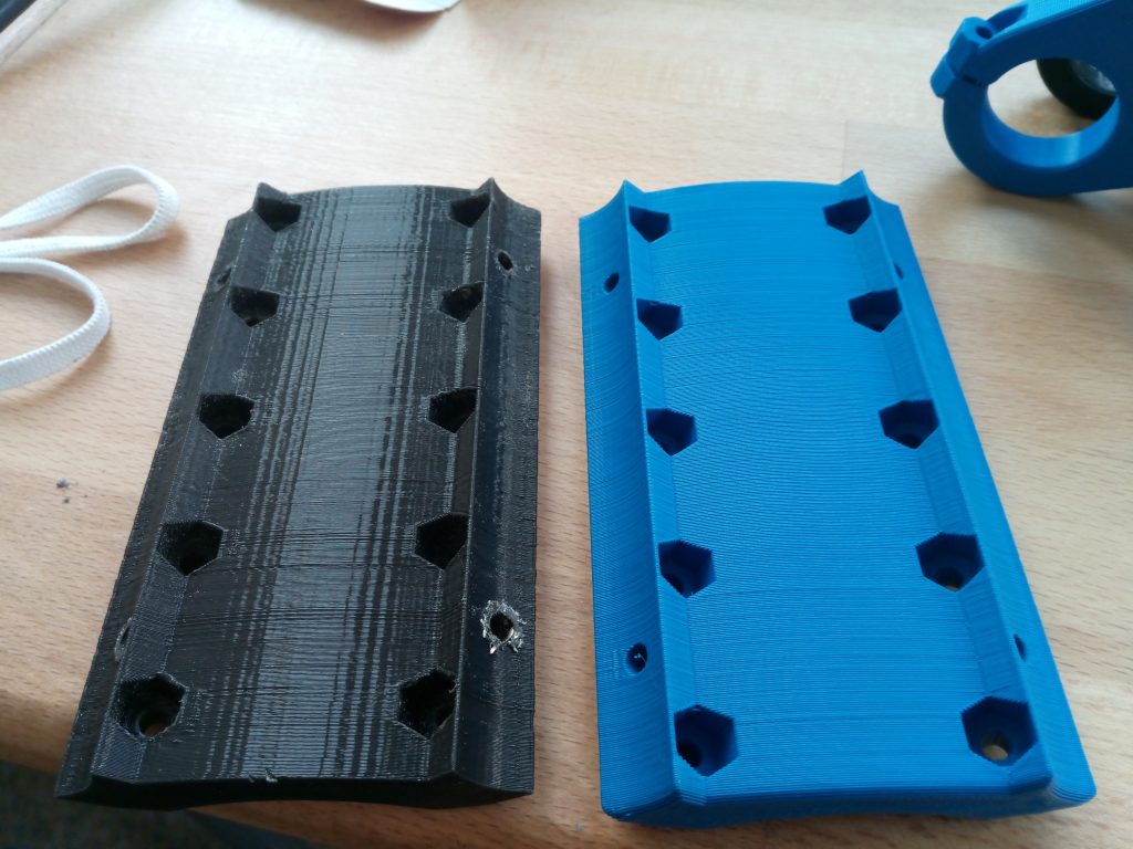
2. Druckteile

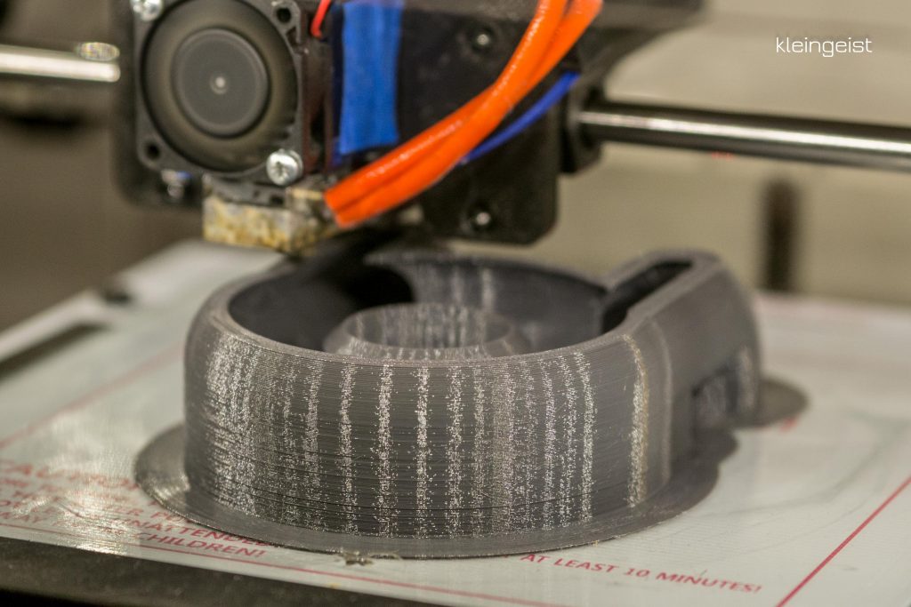
Die gedruckten Teile benötigen je nachdem was für Drucker man zur Verfügung hat und der dafür freien Zeit 1- 2 Wochen. Es ist aber durchaus schaffbar und macht einen Teil der Faszination für diesen Router aus. Die Teile sind gut konstruiert und lassen sich auf einem kalibrierten Drucker sauber herstellen, ohne große Nachbearbeitung. Gedruckt habe ich sie mit den von Ryan empfohlenen Einstellungen. Aufgrund der langen Druckzeit empfehle ich bei einer Schichthöhe von Oberhalb 0,2 mm zu bleiben. Die Genauigkeit ist vollkommen ausreichend und die Druckzeit bleibt erträglich. Verwendet hab ich PLA und PETG von „Das Filament“ genaueres dann in der Teileliste. PETG ist zwar zäher aber leider auch flexibler deswegen ist die PLA variante zu bevorzugen, wie ich später feststellte.

3. Mechanische Komponenten

Je nachdem wieviel man ausgeben möchte kann man hier natürlich auch hochwertigere Komponenten verwenden. Ich habe mich für Edelstahl entschlossen da ich auch die Bearbeitung von Aluminium im Sinn hatte.

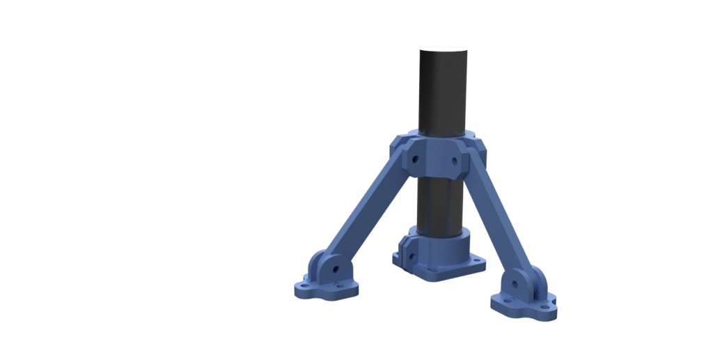
Die größe des Routers spielt eine entscheidende Rolle. Möchte man Aluminium oder Komposite verarbeiten sollte man unter einer Gesamtgröße von etwa 70 x 70 cm bleiben. Umso kleiner umso stabiler wird das ganze natürlich. Auch die Höhe wird vom angestrebten Verwendungszweck mitbestimmt. Möchte man die MPCNC als 3D Drucker verwenden ist es hierbei jedoch sinnvoll mindestens 10 cm finale Bauhöhe zu bekommen. Ich habe mich für eine nutzbare höhe von 15 cm entschieden. Um Aluminium und GFK fräsen zu können hab ich mir einen erhöhten Arbeitstisch gefertigt, der dann die Höhe zum Mittelpunkt der sich kreuzenden Streben minimiert. Die Standfüße sind natürlich dann trotzdem lang und geben etwas nach aber zumindest das Spiel im Werkzeugkopf und somit die Abweichung am Fräser ist minimiert und die Vielseitigkeit bleibt erhalten.

Die Rohrlängen können mithilfe dieses kleinen Tools ermittelt werden. Simple MPCNC Calc

In meinem Fall hab ich also bei einer Gesamtgröße von 70 x 70 cm eine Bearbeitungsfläche von 40 x 40 cm und eine Bauhöhe von 15 cm. Meine Tests bestätigen dabei eine gute Fräsleistung sowie genug Raum um das ganze als 3D Drucker zu betreiben. Die Werte für die Rohre können natürlich gerundet werden um den Schneidvorgang zu vereinfachen.

4. Elektronische Komponenten

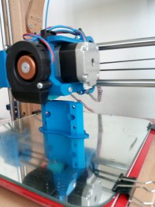
Ich habe die empfohlenen Steppermotoren verwendet. Da hier zwei Stepper pro Achse werkeln bringen diese ausreichend Drehmoment für alle bisher getesteten Materialien und Geschwindigkeiten mit.

Als Steuerung kommt ein RAMPS 1.4 board und ein originaler Arduino Mega 2560 zum Einsatz. Zusammen mit den DRVs ist das auch die empfohlene Konfiguration. Alternativ könnte man ein Smoothieboard verwenden welches ein wenig intelligenter beim Fräsen vorgeht und feinere Abstufungen bei runden Formen ermöglicht. Dafür gibt es allerdings keine vorkonfigurierte Firmware und auch der Preis ist logischerweise etwas höher. http://smoothieware.org

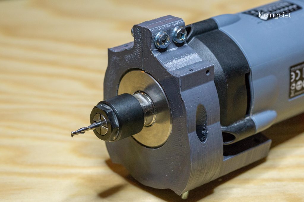
Die Kress FME 800 ist eine gute Wahl als Frässpindel. Genügend Leistung, geringeres Gewicht als bei Beispielsweise Suhner und präzise im Rundlauf. Ich hatte bisher noch nicht beobachten können das die Leistung der 800 Watt Version nicht ausreicht. Selbst bei schnellen Aluminium Schnitten ist die Drehzahl nicht eingebrochen zumindest mit den bisher verwendeten 3mm Fräsern. Die Lautstärke ist recht hoch und liegt etwas Oberhalb des üblichen Staubsaugers aber da hilft wohl nur eine HF Spindel. Zu dem Thema hatte ich mich kurz informiert und was qualitatives und halbwegs bezahlbares konnte ich nicht finden, bis auf die dubiosen „Chinaspindeln“. Dennoch scheint es eine ganze Menge Leute zu geben die mit dieser Alternative zufrieden sind.

Bei der Stromversorgung hab ich mich für die 30 A Version entschieden. Das ist prinzipiell nur nötig wenn man später 3D Drucken möchte und grössere Heizbetten verwendet. Für gewöhnlich reicht ein Netzteil mit um die 10 A (12V) locker aus.

5. Kleinteile und Zubehör

Optional aber hilfreich sind Sachen wie Endstops für Werkzeugwechsel, Energieketten für die sichere Führung der Kabel und ein LCD mit SD Karten slot für PC freien Betrieb.

6. Teileliste mit Link

Hier ein Beispiel zu den verwendeten Komponenten und wo man sie bekommt. Ich habe gute Erfahrungen mit diesen Lieferanten gemacht daher liste ich sie auf. Bitte trotzdem selbst prüfen ob die Teile geeignet sind. Dafür kann ich keine Garantie geben.
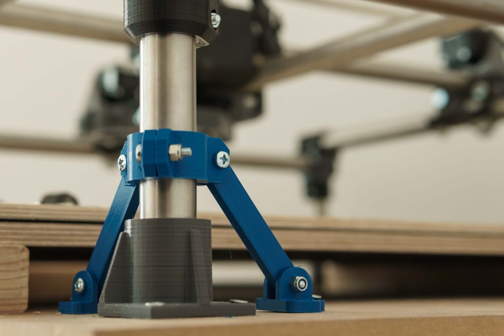
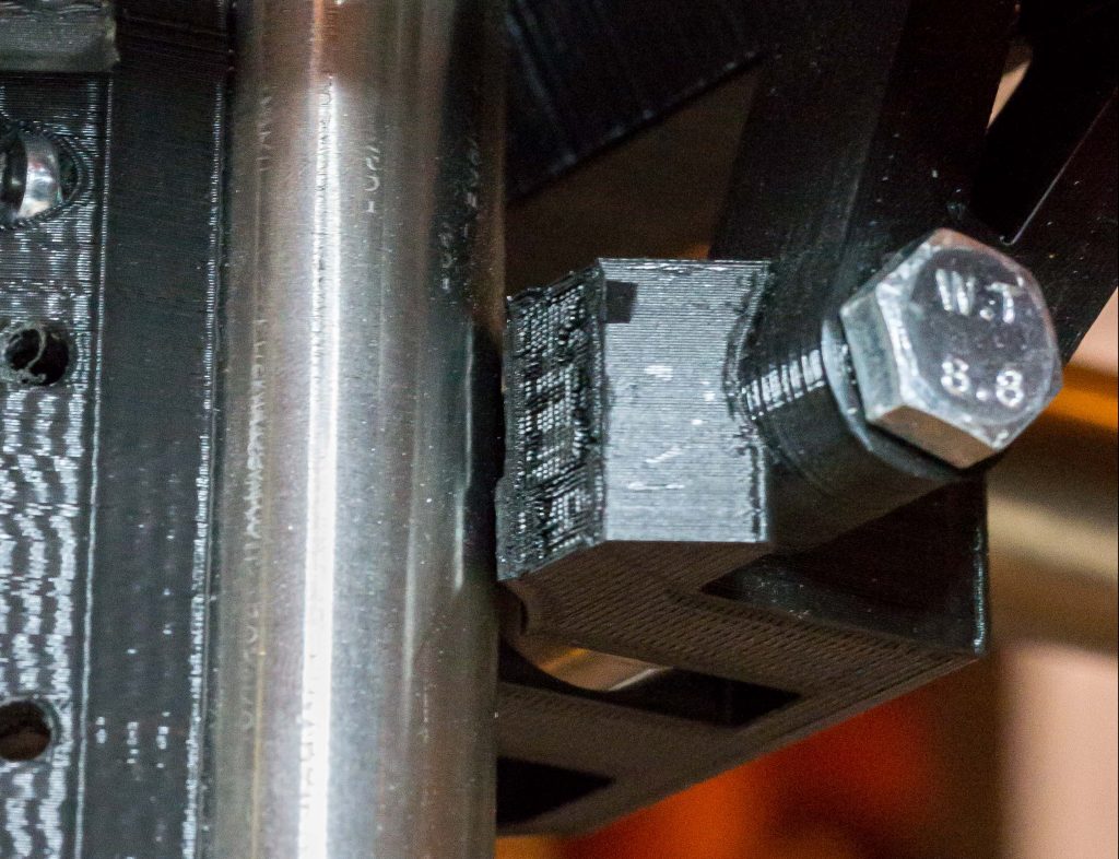
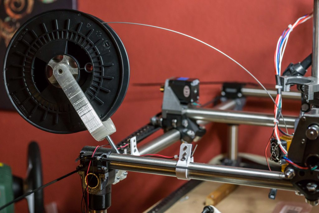
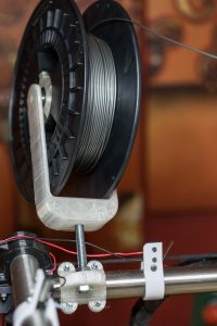
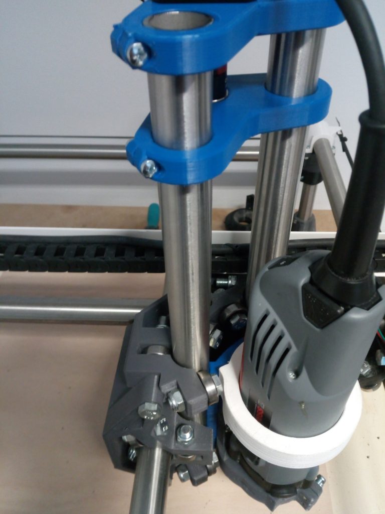
Desklamp „century“

It has been a while since the last post and the reason for that is the design and manufacturing of a desk lamp. The initial design differs from the final product as the whole process has been simplified a little. I gathered materials for three of them so the first one will serve as a production test to find out if everything fits. Once finished I am going to include the finer details.

Centuries desk lamp

The pedestal is a 3D cnc piece made from walnut here. It has been changed to a more simple round apple wood base with a 10mm phase cut with a bandsaw. Since the apple wood has a real nice grain I like it even more by now. I made three of them and one is probably going to be machined on a lathe by a friend to get closer to the intended design.

Desk lamp parts

The switch case mounted in front is going to be replaced by an inline switch, this also eases up the amount of needed prints. The joint for the arms above has been redesigned and is now clamping instead of a bolt through design with three possible positions. I have not tested yet if the clamp produces enough force to hold the arms and the lampshade with all the components. I hope this works out well.

desk lmap arm clamp and joint

The arms should be made out of aluminium and I found some nice bars I can make them of. The first step will be to mill them out of some old wood planks I got. That is a good test to see if the dimensions of the parts work together well from a design perspective. The final arms are then milled as intended when the design is validated.

The lampshade is 3D printed and adapted to a regular E14 lamp socket. The threads came out usable on first try and I will keep those first parts.

desk lamp lampshade

The project was started in july and was delayed because I had to build the MPCNC first but I´m almost finished by now. Pedestal and arms need to be cnced and some of the knobs are left to be printed.