C-Beam „touchCNC“

Ich hatte einiges probiert als Steuerung für die Fräse. Die meiste Zeit hatte ich Openbuildscontrol https://software.openbuilds.com auf einem kleinen Wohnzimmer PC (AMDFusion E350) laufen. Das funktionierte gut so lang wie beim Trochoidalfräsen oder Fusion adaptive nicht allzu viele Pfadsegmente gestreamt werden müssen. Das passiert selten aber wenn es passiert stottert der Ablauf was wiederum für den Fräser eine Belastung sein kann. Einen große Rechner wollte ich aber auch nicht wirklich daneben stellen also fing ich, nach der Steuerungslogik in den vorherigen Beiträgen, mit einer integrierten Steuerung an.

:

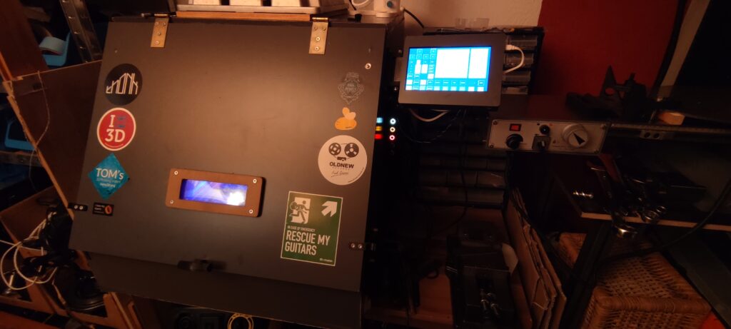
Akt 1 : Openbuildscontrol auf einem Odroid C2 mit TouchVU Screen

Das stellte sich etwas als knifflig heraus. Die Entwickler rieten schon von dem Einsatz auf arm Rechnern ab aber probieren muss man es jetzt ja trotzdem mal.

Ich habe draufhin das Script für die Installation auf dem Raspi auf den odroid c2 und armbian angepasst. Das lief dann irgendwann sogar allerdings musste ich die 3D-Ansicht deaktivieren. Somit hat man dann auch keine 2d Preview von irgendwas. Das ganze startete automatisch als einzelnes chrome Fenster ohne Desktop direkt nach dem Start und war sogar, naja ahm, nicht brauchbar. MAn konnte zwar einfach vo neinem anderen Rechenr den zu fräsenden Gcode einfach per Netzwerk auf die Fräse ziehen, da Openbuildscontrol als Server client Web Anwenung funktioniert, allerdings hat man dann nicht mehr viele Eingriffsmöglichkeiten auf dem Odroid. Es beschränkte sich auf Nullen und andere Vorbereitungsarbeiten. Das war mir ein bisschen zu wenig für den Materialeinsatz den man da ins Feld führt (Odroid + VU).

Nach einiger Zeit desintegrierte sich die Installation ohnehin aufgrund irgend eines Updates. Grr…

Akt 2: Vielleicht könnte man irgendwie doch was eigenes Schreiben?

Das war zunächst eine recht gewagte Vorstellung, jedoch war das auch nicht das erste mal das ich mich irgendwo fluchend durchgefräst hatte. Python kannte/konnte ich ja schon ein klein wenig von vorhergehenden Abenteuern und TKinter bin ich auch schonmal begegnet als ich die Minianwendung für meinen Zweibeinroboter geschrieben hatte. Ein passendes Buch zu Python 3 hatte ich auch seit geraumer Zeit und dieses erwies sich durchaus als nützlich.

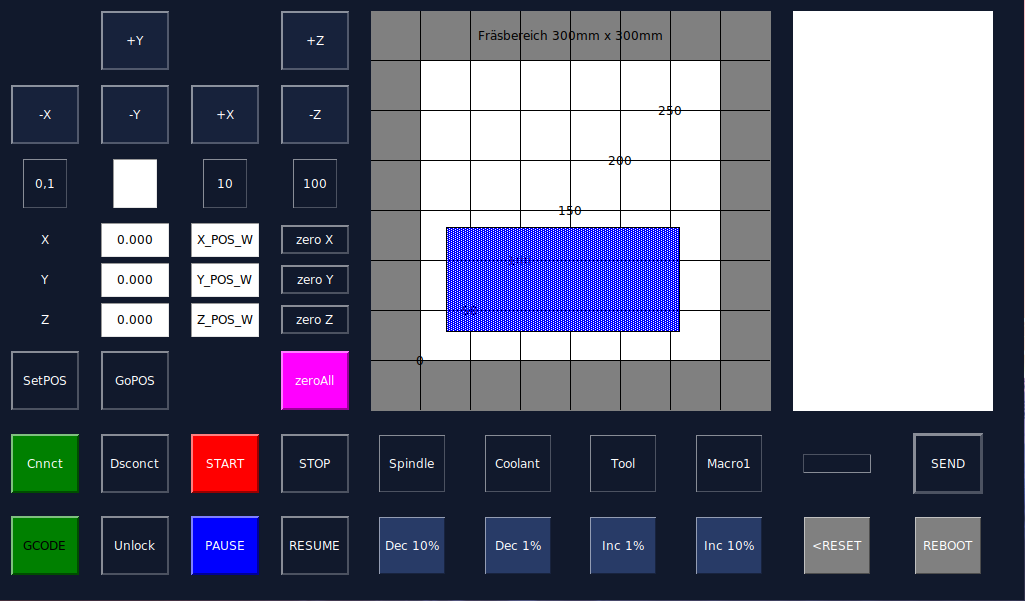
Einige Tage später hatte ich dann die erste einfache Version die auf den Odroid übertragbar war fertig und irgendwie fand ich das alles sehr sehr chic. Ein paar weitere Tage später lief auch der Gcode so weit rund und das Nullen und Joggen funktionierte auch super. Einzige einige Zeilen schien er dann und wann zu verschlucken und Arcs und ähnliche exotische (:D) Gcode Befehle waren ihm zunächst auch Fremd.

Updates lassen sich einfach über SSH zugriff und einem schlichten „git pull“ befehl ziehen und die NC Files landen per Nextcloud auf dem kleinen Rechner. Durch die minimalen Abhängigkeiten (0) sollte das auf jeder noch so staubigen Distribution laufen.

Der ganze Stolz

Ich gebe zu ich hab bisher trotzdem noch nichts damit gefräst, einfach weil das unter Zeitdruck eine sehr sehr schlechte Idee ist aber ich werde mir Mühe geben das ganze demnächst unter harten Einsatzbedingungen gnadenlos auszuloten.

Diese wirklich tolle Software findet ihr unter dieser Adresse: https://github.com/BKLronin/touchCNC

Danke für ihre Aufmerksamkeit.

P.S.:

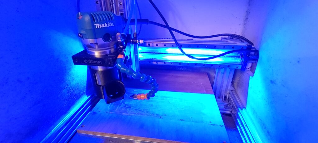
Mittlerweile gibt’s auch eine Tröpfchenkühlung die echt beim Alufinish hilft sowie eine neue Absaugung falls es Mal Holziger wird.

C-Beam Umbau und Gehäuse für xpro cnc v3 CNC controller.

Da ich mich damals für die C-Beam entschieden hatte aber nur mäßig zufrieden war mit den Ergebnissen in Aluminium, habe ich versucht das ganze iterativ an ein gutes Fräsbild hochzumodden und habe erst dann begonnen Komfortfunktionen nachzurüsten.

Stufenweiser Umbau der Führungen

Im Original sind kleinere Rollen im inneren verbaut. Das macht es schwierig die Rollen einzustellen und auch der Ansatzpunkt ist viel schmaler und die Spindel hat es einfacher diese zu verwinden. Daher die Verlagerung der Rollen nach außen und Ergänzung um zwei weitere. Die Platte dafür habe ich auf der MPCNC fräsen können mit vorsichtigen Schnittwerten. (Einzahn Sorotec alu Fräser, ca 200-400mm/min, 1,5 doc volleingriff, ungekühlt@30000rpm)

Danach war das Fräsbild etwas verfeinert also die flanken waren noch nicht „spiegelnd“ aber immerhin konnte ich einfache Teile fertigen.

Im nächsten Schritt habe ich dann doch auf Profilschienen umgerüstet. Es war stark zu überlegen ob das investieren in die Maschine lohnte aber zu dem Zeitpunkt gab es nicht viele Optionen. Da die Führungen relativ günstig waren und der Umbau fast ein Drop in Replacement, hab ich es dann riskiert. Die Halte und Verbindungsplatten sowie die Grundplatte kontn eich ohne Zwischenfälle auf der Vorgängerversion herstellen. Dies beschränkte sich ohnehin auf die Bohrungen (Bohrfräsen mit 3mm Fräser).

Die untere Platte neigt natürlich ein wenig sich zu verformen wenn man am äußersten punkt Kraft anbringt jedoch wollt ich mir die beiden zusätzlichen Extrusionen erstmal ersparen da ohnehin nicht viel Kraft in der Z-Achse zu erwarten war.

In dem Zuge habe ich auch gleich ein Gehäuse aus OSB Platten gemacht Hauptsächlich zur Lärmreduzierung aber auch um die Späne zu kontrollieren. Die Platten kamen von meinem Nachbarn und waren Verschnittreste aus einem Podestbau. Danke Stefan! Das ganze wurde später noch foliert um es haltbarer und optisch ansprechender zu machen.

Das Fräsbild verbesserte sich glücklicherweise dramatisch, nach dem die ganze Maschine auch wieder neu ausgerichtet war.

Das sah dann shcon ganz passabel aus trotz fehlender Kühlung und nur Spanevakuierung durch das Makitagebläse. Innen sieht man einen Adaptive Werkzeugpfad ohne anschließenden Schlichtungspfad.

Umbau der Elektronik

Original kommt nur eine Art Halteplatte für den Xpro CNC V3 von Sparkfun electronics im Ooznest kit mit. Das reicht grundsätzlich um die Maschine in Betrieb zu nehmen. Für so eine kleine Platine plus Netzteil lohnt auch keine Schaltschrank oder irgendwas, wie ich fand.

Original Montageplatte

Daher habe ich das ganze ein 3D- gedrucktes Gehäuse https://www.thingiverse.com/thing:4583595 integriert mit einer Reihe beleuchteter Taster.

Verdrahtung

Das ganze wurde dann angeschraubt und ermöglicht jetzt, Start / Pause /Reset / Kühlung / Spindel An/Aus, wenn alles fertig ist. Es fehlt noch eine kleine FlipFlop Schaltung die das Relais hält wenn ich einzeln Taste. Die Schrittmotorentreiber sind gut gekühlt und die Kabel zugentlastet etc. Die restlichen Kabel müssen noch ordentlich verlegt werden natürlich.

Kontrollpaneel

Fabrikator Wartung und Umbau auf E3D-Chimera zweifarb/material Hotend.

Mein Fabrikator druckt jetzt schon eine ganze Weile recht zuverlässig mit dem E3D V6 Hotend als Bowdenumbau. Etwas überdimensioniert, hat er damals ein Smoothieboard erhalten um die drucke ein wenig feiner und sicherer gegenüber dem Ramps zu machen, jedoch ist das Lautstärkelevel durch die A4988 sehr nervig. Daher die Idee das final nochmal umzubauen und das herumliegende Chimera-hotend mit zwei Titan Extrudern einer Bestimmung zuzuführen.

Als Board kommt wahrscheinlich ein Megatronics, bestückt mit DRV8825 aus der demontierten MPCNC, zum Einsatz.

Die neue Frontplatte sollte die Hitze des Chimera gut abführen und sieht auch recht wertig aus trotz des leicht stumpfen aber scheinbar unzerstörbaren Sorotec Fräsers. ( Versehentlich 5mm doc Vollnut bei 900mm/min für gut 200mm)

Hauptplatte mit erhobenem Sockel für den Chimera.

Schnappverschluß auf Thingiverse veröffentlicht

Einfacher Verschluß, ursprünglich für meine CNC-Einhausung gedacht. Vorteil ist das heranziehen der Tür an die Dichtlippe der Isolierung und die gute Vibrationsdämpfung.
STEP included!

https://www.thingiverse.com/thing:4580112

Openbuilds C-beam from Ooznest

I had the demand for some more serious aluminum milling. I did that with the MPCNC before and it was kind of okay but I wouldn´t like to mill higher part counts with it. The spindle gets  hot after some time and leads to more flex in the toolhead. It´s not made for aluminum so I looked around for a more suitable platform.

I found the openbuilds C-beam machine to be nicely designed and versatile enough to be worth adding to my machinepark. I looked around for a europe based shop and found openbuilds poland  , v slot europe and ooznest .

I decided to go with the ooznest version as they had the best full kit. I didn´t wanted to source all the parts from here and there. Sometimes it´s nice to have a complete package 🙂

The sipment was fast after the payment went trough and so I had a first look at the package today. All was nicely packed and labeled according to the build section like X, Y and Z Axis. The printed parts for the power supply and the controller board looked pretty nice and felt solid.

Can´t say much yet but a real manual would be more comfortable than a build video. It´s way faster to look at a drawing than to forward, play, stop, rewind, play, the buildvideo 😀

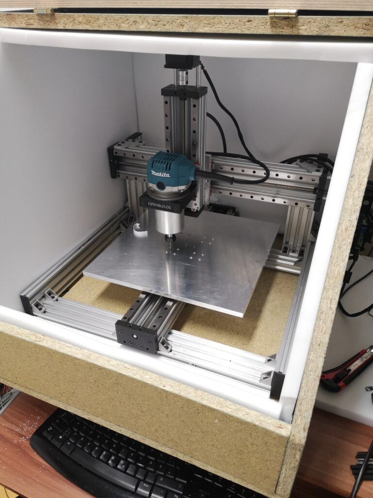
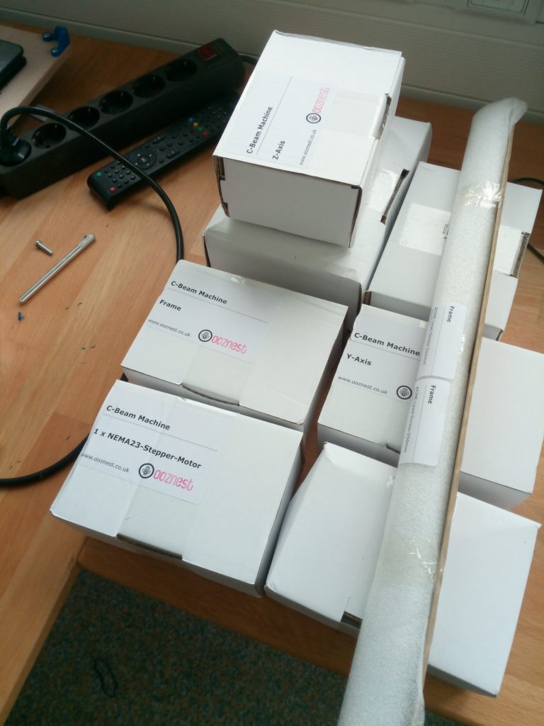
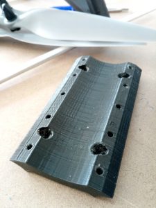
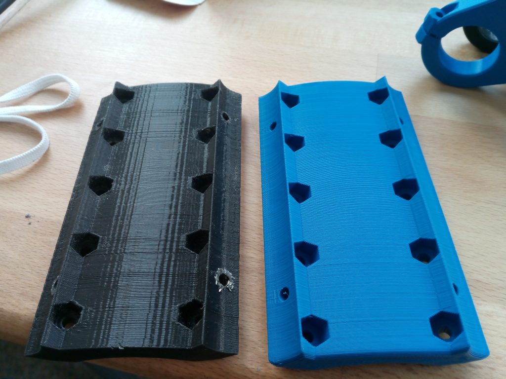
Ready for assembly 🙂

MPCNC- maintenance and rework of the z-axis

I currently got some problems with drilling holes again. It seems there is something odd in the Z- axis. I didn´t assembled it carefully enough. I suppose that the spindle isn´t lowered in a straight line, instead it is tilted on the way down pushing the endmill into the material sideways and ripping a hole into my plywood.

I´m using this as a reason to reprint the tool- and steppermount.

When I originally build the MPCNC I had no drillpress and  the terrible idea to tap a M4 thread into the stainless. This is a bad idea as it clearly makes the alignment of the screws in the tool mount to the conduit almost impossible.

I redrilled the holes and I am now using the original path with the nut traps inside the conduit. Along with the adjustment of the leadscrew this hopefully improves the precision and rigidity of my z-axis.

Finished toolmount replacement. The one on the left was printed with an pre R17 BCN3D Sigma and the right one printed with my DIY printer.

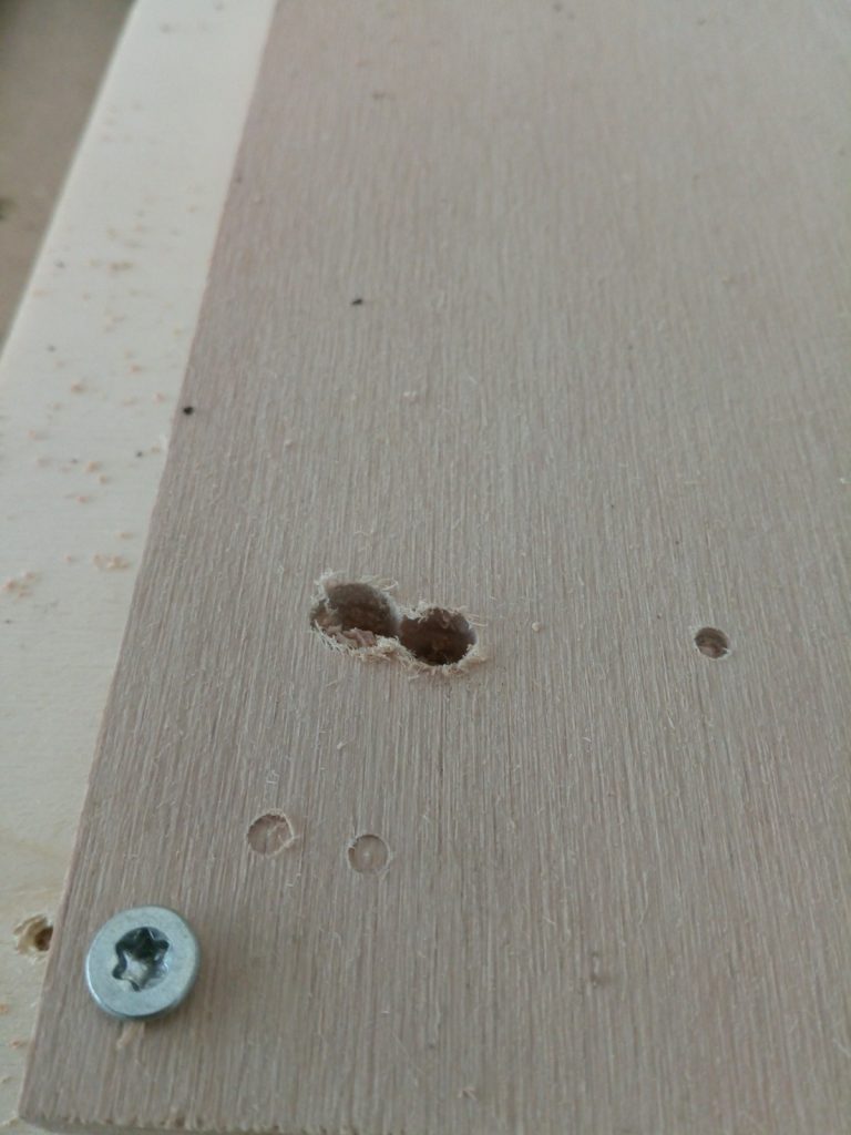
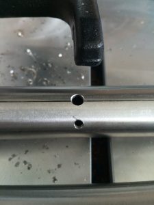
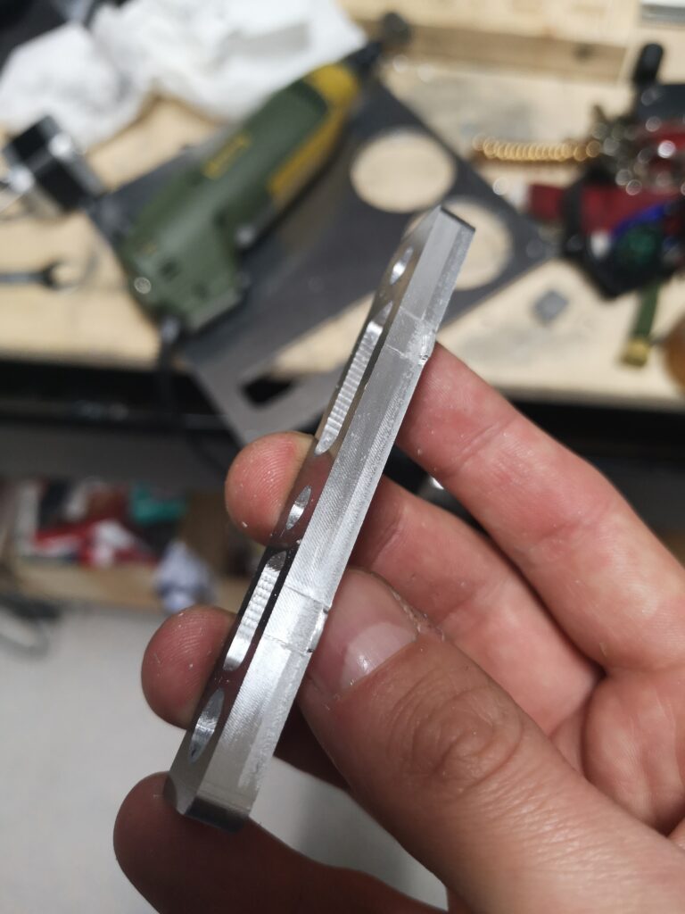
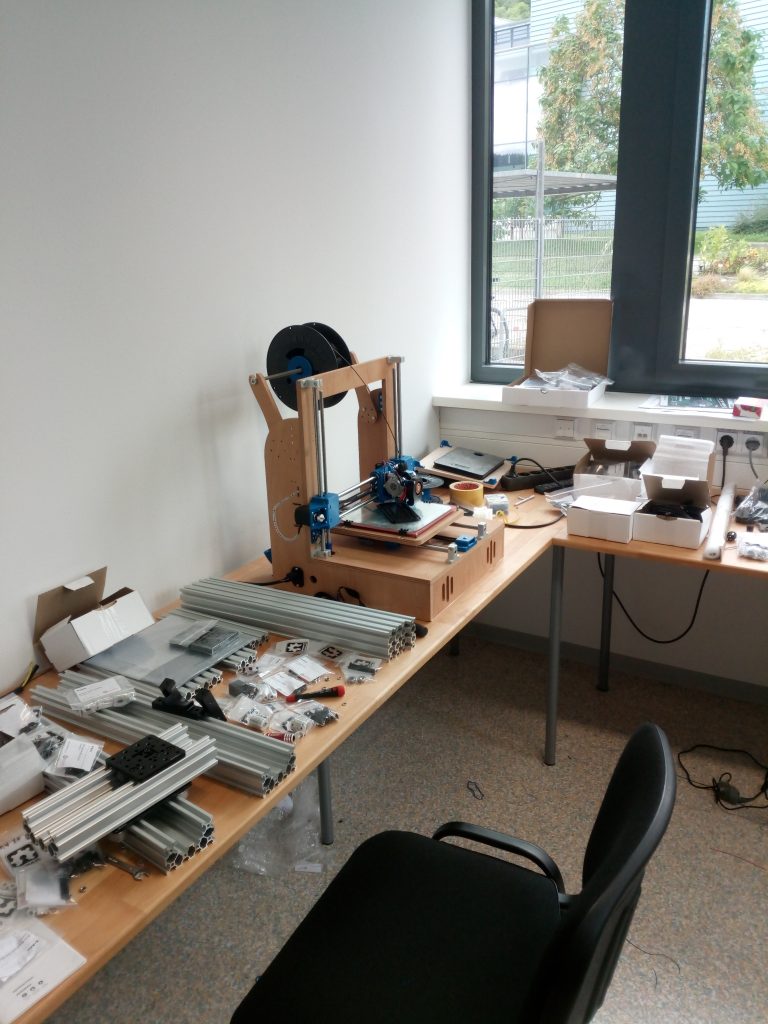
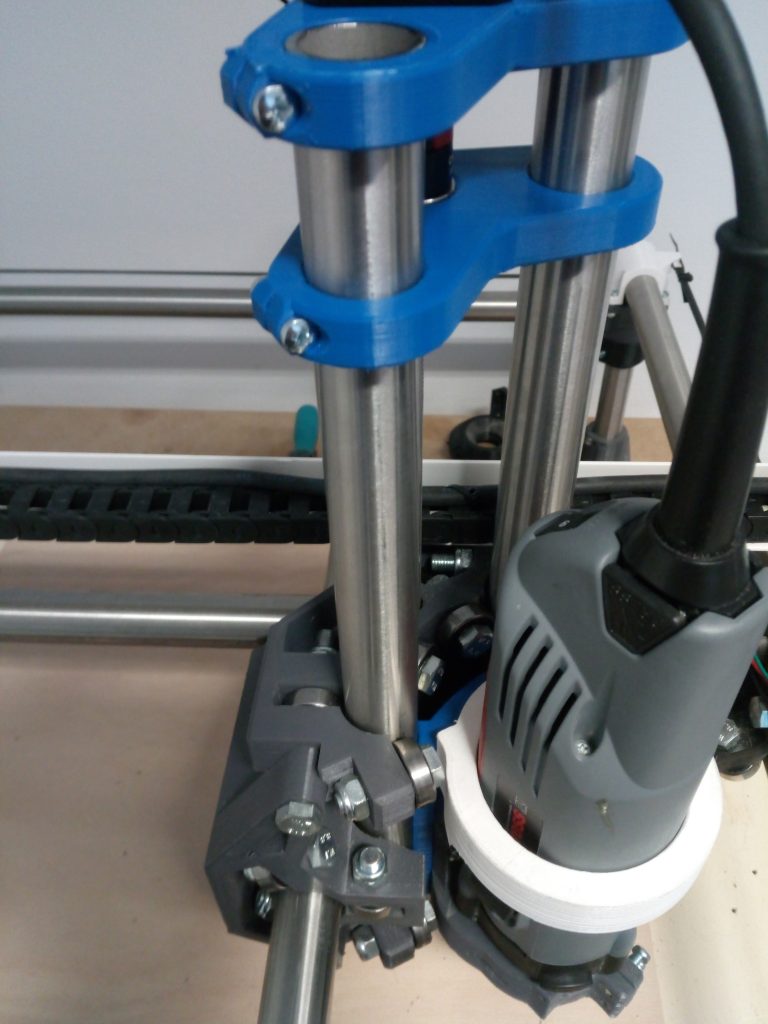
Now everything is assembled again. The tubes are now „perfectly“ straight and parallel. I used a glass plate to verify the alignment.

I did a short test run and I had the same result as before. A nice circular vibration and a not very pretty drill hole. I´m using a diamond cut endmill at the moment and went successfully through two sets of printer frames. I´ve been told in ryans formum (viscious1.com) that diamond cut bits are everything but ideal to dive 12mm into beech plywood. They are very robust so they were the only ones that survived when it came to an error. They are compressing the shavings within the hole and that leads to more and more pressure hence the heat rises and the endmill escapes in the circular movement.

In the past I ordered a endmill from sorotec which broke after some drilling operations. That left me confused what the error might be. I also tried a shorter endmill originally for aluminum which transported the shavings quiete nicely but was too short.

I ordered new endmills again and hopefully all the possible errors caused by the machine are gone and I get my drill patterns and contours out of one endmill.

Wish me luck!


MPCNC – finished dust shoe system

Inspired by one of my readers I had a look  at the dust shoe for the Kress again. I redesigned it completely and got rid of the additional tubes and clamps. I thought that it would be a good idea to have a highly flexible part between vaccum and CNC. If I had ordered the 20mm silicon tubes it may have worked as well but reducing parts is allways priority.

So in the end we got a pretty classic dust shoe here. It doesn´t have a brush at the bottom as it seems to work pretty good at the moment and I really like to see the endmill. However I included three holes at the bottom for a later brush design.

It works pretty good with lighter materials but GFK, aluminum or similar are not fully sucked up.

It has been printed in 0,3mm draft quality for testing purposes.

It has been released on thingiverse here http://www.thingiverse.com/thing:2119491

Now also available in my shop here

Building a MPCNC part 3- cutting

In order to find a suitable endmill I had to understand the principles involved first. That led me to feeds and speeds. The difficult part was to determine the limits of my cnc. I already had a look on that topic when I chose my Spindle. It has a minimum RPM of 10000 and a maimum of 29000 RPM so I decided to go for a 2 flute endmill with a diameter of 3 mm from cnc-plus.de. More on the calculation later..

After testing the gcode and finding out if the steps/mm of the steppers are dialed in correctly I used a simple ruler to check. Josef Prusas stepcalculator gave me 160 steps/mm and that resulted in the correct distance of movement with my 20 tooth pulleys. As I couldn´t  set the parameters from the graphic display I had to reflash the Marlin firmware.

I used a M8 threaded rod like suggested in the original plans. It is not meant for machine operations and so It loves to do what it is designed for. It binds pretty often, resetting the z axis position and making sudden, unexpected deep cuts as shown in the video below. It is the straightest rod I could find and it is well greased but it was necessary to lower the acceleration and speed. I only had this one piece of hardwood and I wanted this to suceed. I´m trying to get the speed back up again because the milling took ages (1h15min) because of the adaptive clearing and the many retractions of the tool head.

The 3D printed rigid couplers didn´t worked to well for me so I ordered a jaw coupler also from http://cnc-plus.de to make it more reliable.

In conclusion : I liked the results of the cuts and they were somehow thrilling. The accidentially super deep cuts showed that I can go much deeper than 3mm in one pass with hardwood. The method used here was also a test for the ultimate goal for cutting alumium sheet and composites.