Changing the site-language

Changing the sites primary language to ease up the writing process and get more into detail.

Nach langem überlegen habe ich mich entschlossen die Sprache der Seite auf natives deutsch abzuändern, dadurch kann ich die eine oder andere Sache doch genauer beschreiben und gewinne etwas Zeit bei der Beitragserstellung.


C- Beam -finished

As promised, some pictures from the finished machine.

I used some plywood as the buildplate that I had in stock. A wasteboard needs to be added.

The power supply with the neat little lcd voltmeter. I send a notification to ooznest regarding the not so perfect crimp connections and they will look into it.

The wired controller. It was pretty noisy at the beginning but after some e-mails with the very kind and fast support at ooznest we narrowed it down to a single deffective fan. Could have happened during the build process or during shipping, despite the good packaging. Ooznest offered a replacement so thats not a problem anymore. I initially thought that the fan itself creates the unpleasant noise by design but the bearings were defect so one of them ran unsmooth.

The spindle in position, I had to use an adapter from the 71mm to 43mm Euro mount. This might work for the first cuts. Would be nice to have a suitable option in the shop for a 43mm tool mount. It is stiff enough for now.

The first test cuts are still ahead so I can´t really say how it compares to a MPCNC just yet.


MPCNC – „Cornerdefender“

My MPCNC showed some significant flex on the four main feet. I wanted to solve this quickly with small amounts of material and without additional hardware, except screws.

It might look kind of funny and when you already modified your corners in some other way or got them low, the aren´t necessary I guess. If you still got most of the original parts, this little gem will help 🙂

Bring the two feet in place, screw them down and the clamp will bring up the tension on the struts.

Files Include modified feet.

https://www.thingiverse.com/thing:2548942

Printed Algae Bioreactor

I thought about building a automated plant care system for some time now. The main purpose was to grow camelia sinensis in a controlled environment, as my three attempts of growing it in a living room or balcony all failed after a year. I was unable to keep the conditions constant enough it seems. I gave up on that, as the grow rate of tea is too low to cover the necessary quantity anyway.

Instead I´m trying to revive my biotechnolgy knowledge and start a printable bioreactor design for cultivating algae. It is not targeted towards a specific species or purpose yet. The first goal is to test the printing process and finding a suitable material with a good transmission and suitable wavelength passthrough. Clear PETG should work as a starting point.

A quick sketch of the concept. The flattube design enhances the surface and therefore the optmum light yield.

I´m searching for suitable equipment that can be sterilized right now.


C-Beam – general build experience

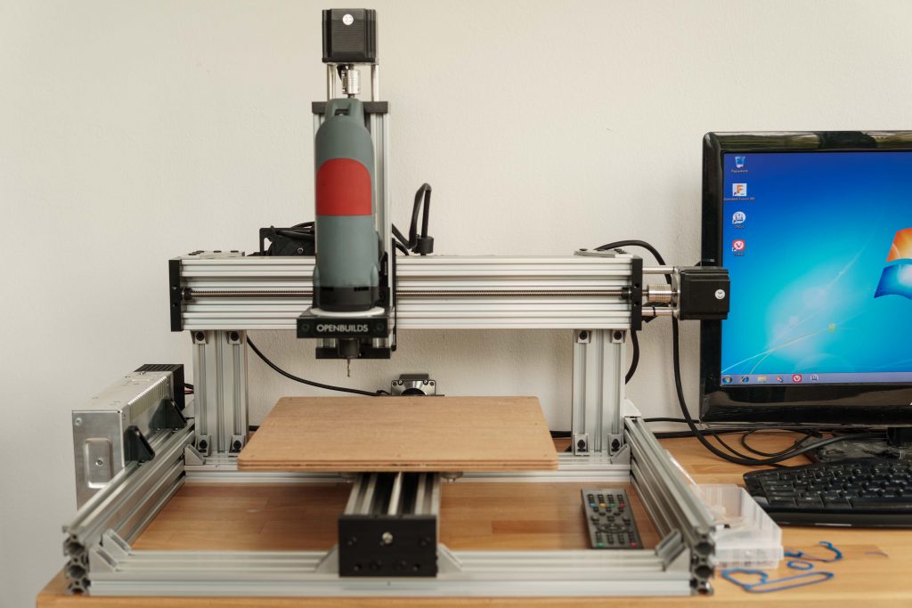
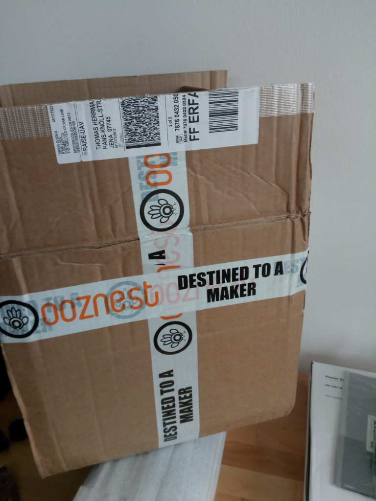
I finished my C-Beam kit from Ooznest some days ago and I thought you might be interested in some of the „issues“ during the build

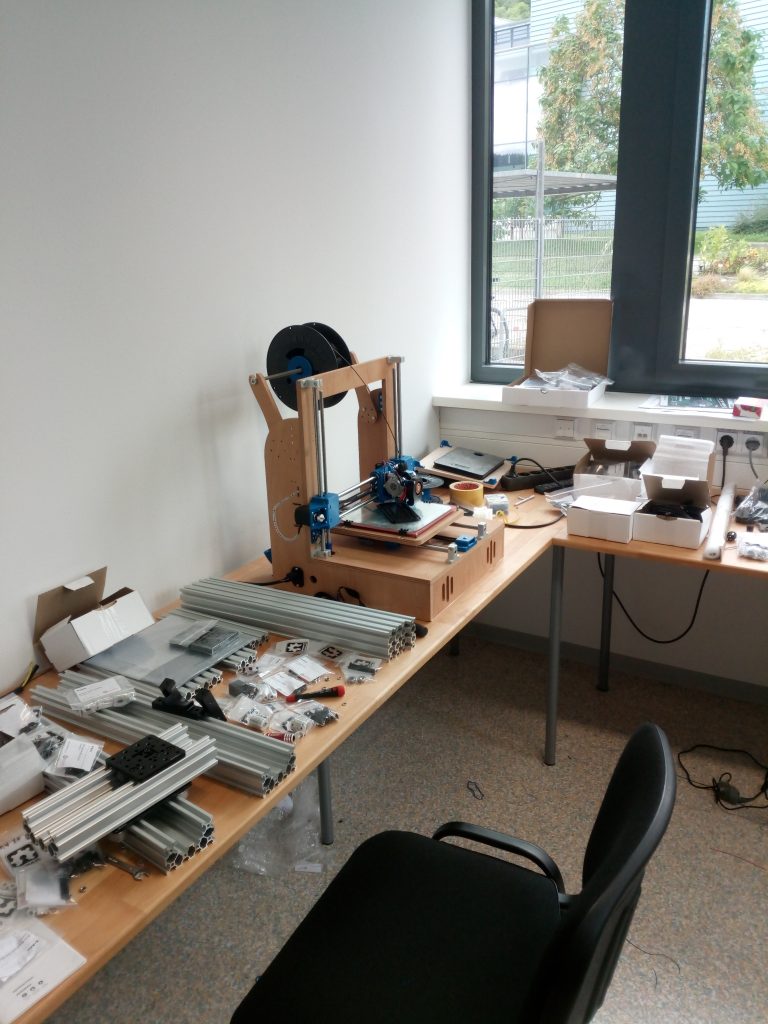
First of all, it has been a big pleasure to build this machine. When you´re designing things yourself most of the time there is a point where you just value a well thought out kit that just fits, as expected from a aluminum profile kit. 😛

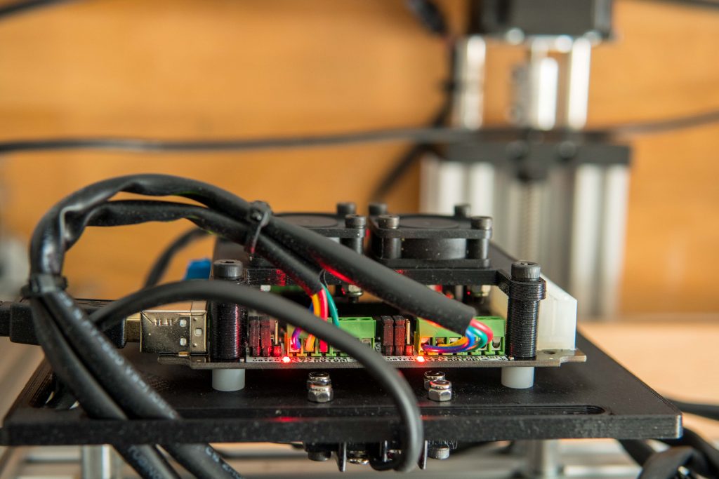
It took roughly two afternoons to get everything together, followed up by some additonal hours of choosing the right software and adjusting the settings. Hendrik found a nice little programm called cnc.js. I had a look at the standard solutions openbuilds suggested and chllipeppr but they didn´t seemed quite right. It worked straight away and despite I haven´t tested it yet with a real cutting job I can really recommend it.

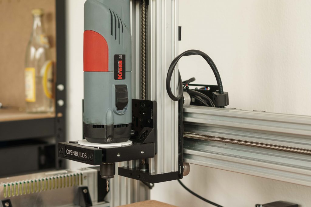
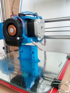
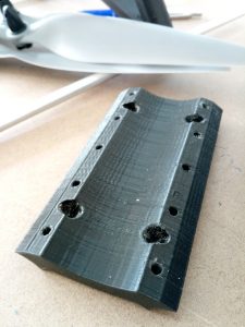
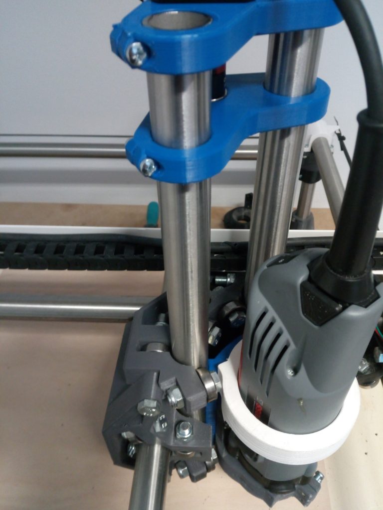
As I´m using the Kress from my MPCNC for testing purposes on the C-Beam I had to do some minor modifications to the tool clamp. I had to get it lower than the intended mounting point and all I had to do was grinding the screws a little down on the edges.

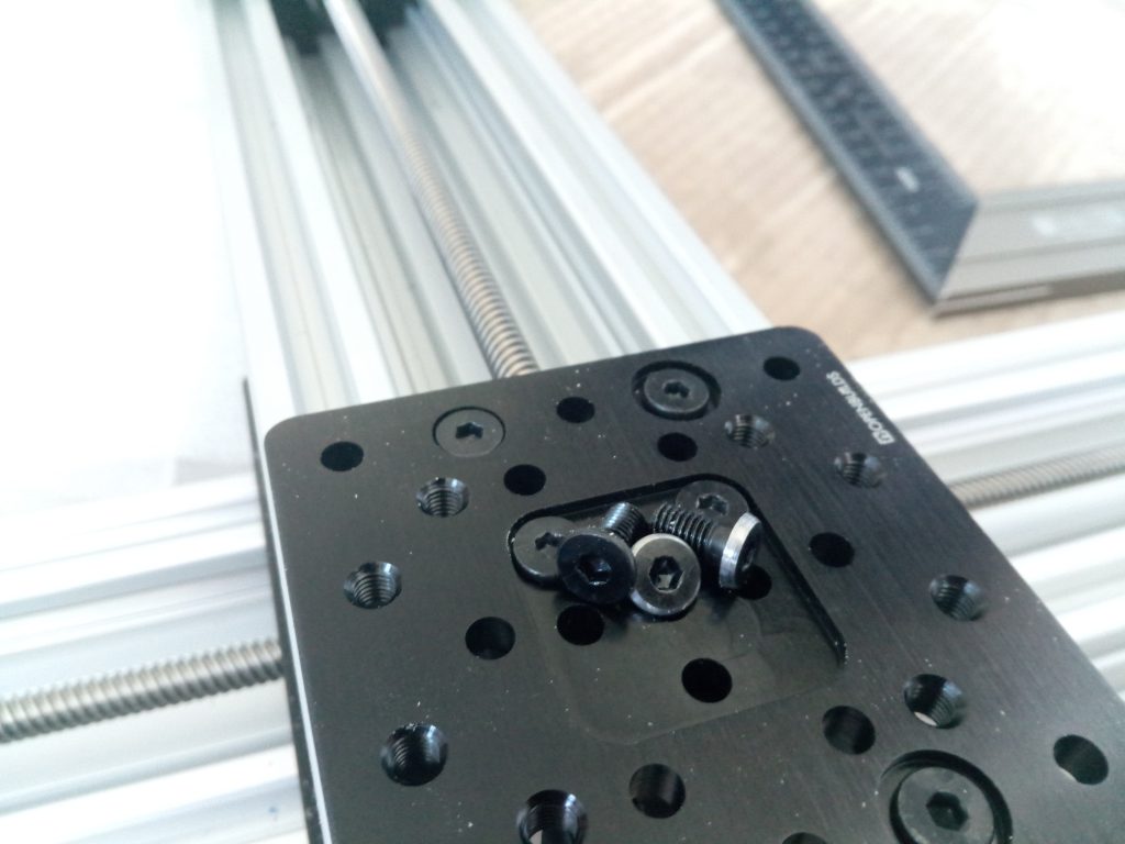
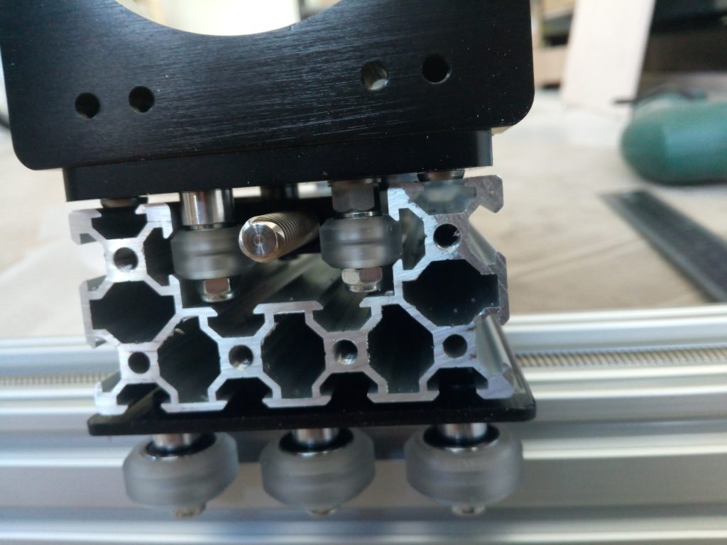
That way It was possible to screw the clamp from the backside of the plate securely. Not as good as the corners that are intended for this but it should work. At least two of them are securing the clamp from above.

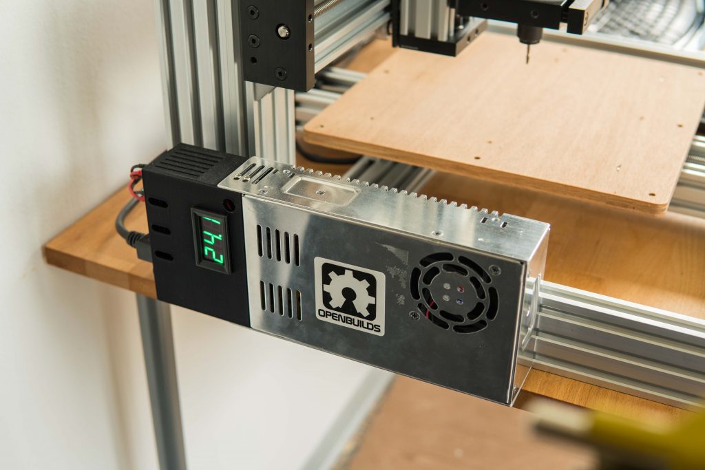
What I didn´t liked so much and I suppose it´s not a common thing with the kit is the quality of the supplied cables. They were crimped on the isolation and that meant they didn´t had any reliable contact to the PSU. After three seconds the PSU switched off. My first thought was that the PSU was faulty and the second was that I might had connected something wrong. As I repeatedly check connections before I power something up I usually suspect the error elsewhere. 🙂

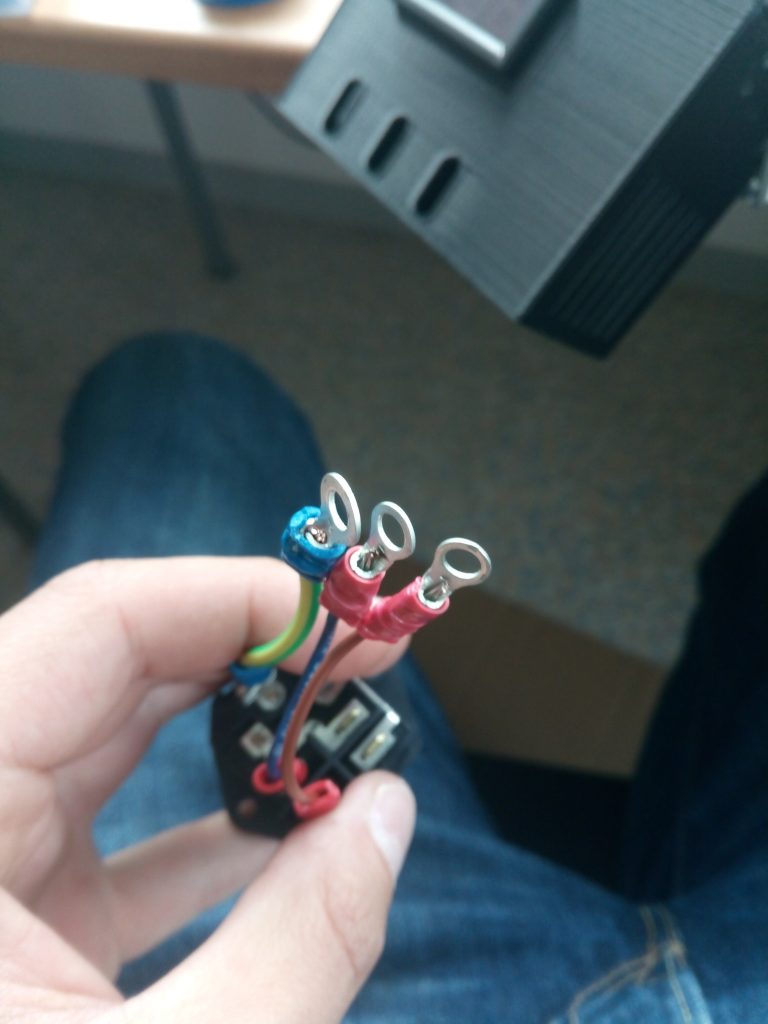
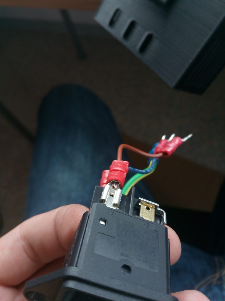
The bare metal shoudln´t stick out at the front and crimping the isolation leads to missing pressure on the cable itself causing a loose connection. I corrected this to get it stable and safe  and everthing works fine now.

Those were the only two points I had to modify. Everthing else went smoothly. Pictures from the final machine will follow soon 🙂

Openbuilds C-beam from Ooznest

I had the demand for some more serious aluminum milling. I did that with the MPCNC before and it was kind of okay but I wouldn´t like to mill higher part counts with it. The spindle gets  hot after some time and leads to more flex in the toolhead. It´s not made for aluminum so I looked around for a more suitable platform.

I found the openbuilds C-beam machine to be nicely designed and versatile enough to be worth adding to my machinepark. I looked around for a europe based shop and found openbuilds poland  , v slot europe and ooznest .

I decided to go with the ooznest version as they had the best full kit. I didn´t wanted to source all the parts from here and there. Sometimes it´s nice to have a complete package 🙂

The sipment was fast after the payment went trough and so I had a first look at the package today. All was nicely packed and labeled according to the build section like X, Y and Z Axis. The printed parts for the power supply and the controller board looked pretty nice and felt solid.

Can´t say much yet but a real manual would be more comfortable than a build video. It´s way faster to look at a drawing than to forward, play, stop, rewind, play, the buildvideo 😀

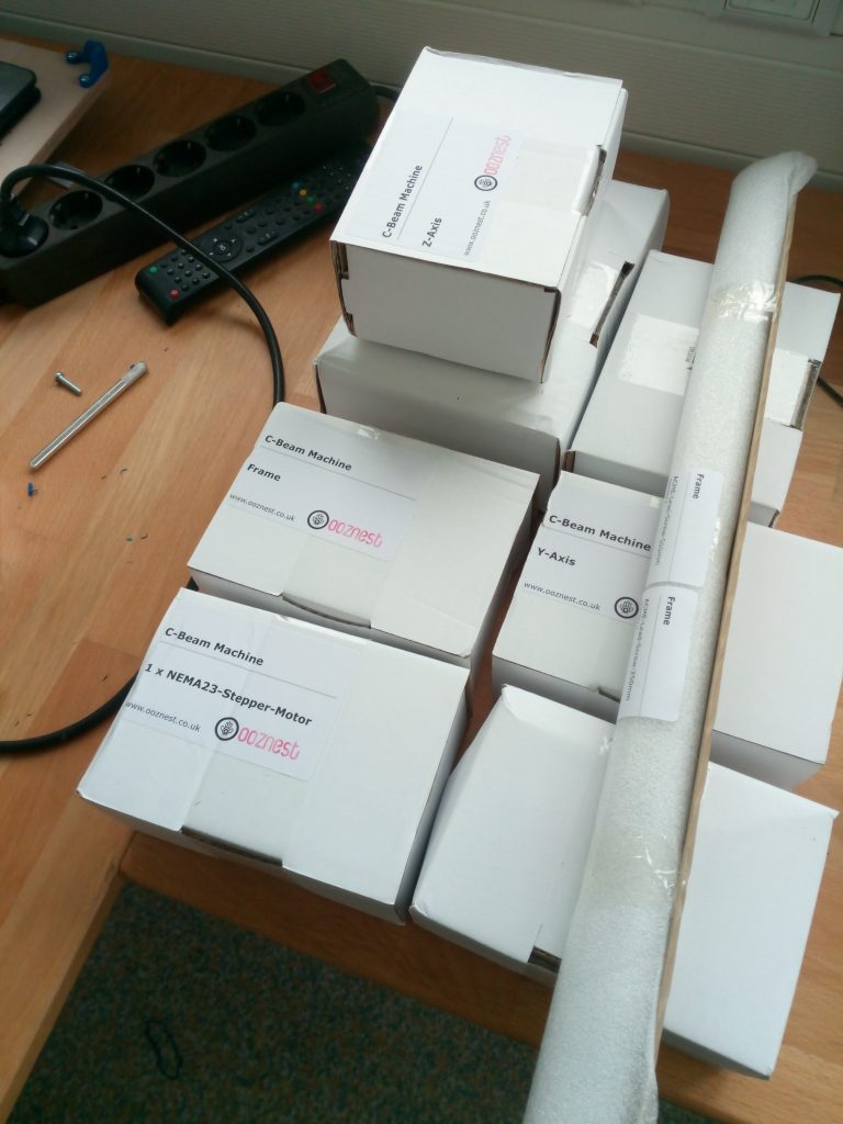
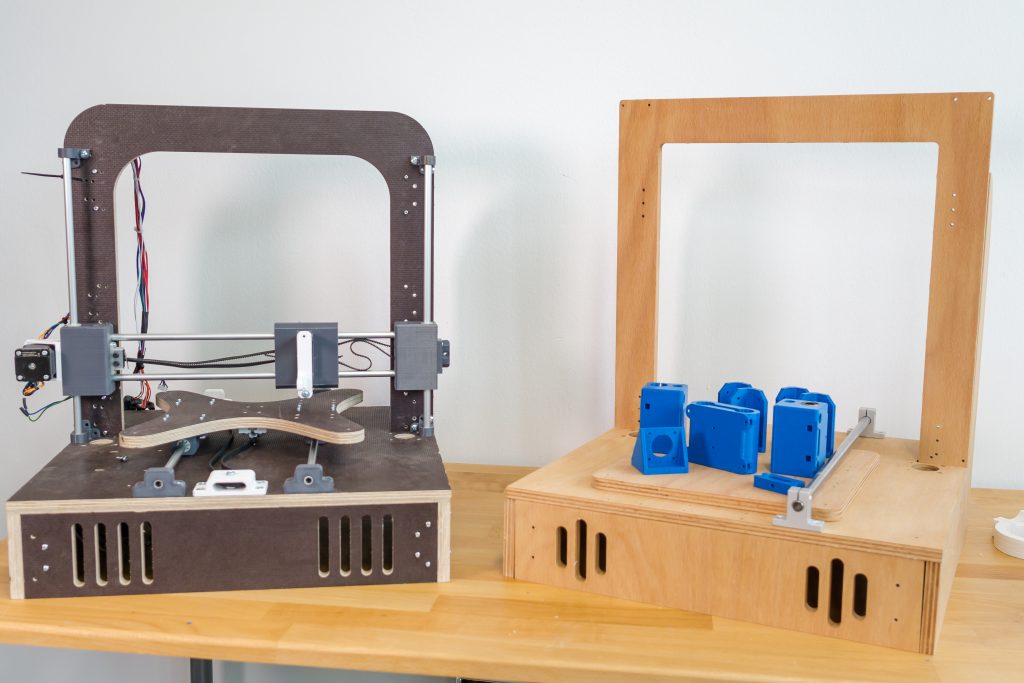
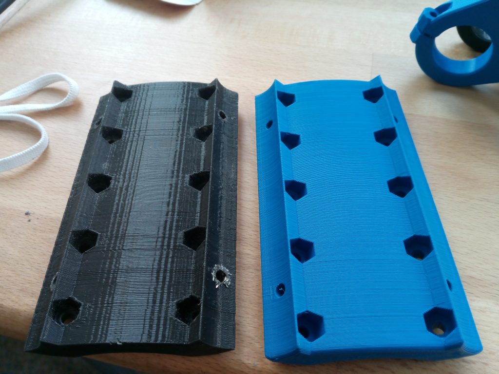
Ready for assembly 🙂

MPCNC- solved drilling issue

Surprise! I had a common chip clearance problem. I considered this as a cause from the beginning and also got some tips from the vicious1..com forum. I milled two complete sets of 3D-printer frames without problems so I couldn´t  believe that this was really the cause.

I drew a test pattern and managed to get it right with an additional ,5mm helical drilling movement. That seems enough for the chips to clear the hole.

I don´t have that much time to get into those issues but the parts didn´t came out perfectly rectangular yet. I tried to manually adjust the stepper position before powering it up but thats still not enough to get the precision I need. I´m using all of the available travel so I´m getting quite a big error in the end.

I need to readjust the frame and the feet as well.

MPCNC- maintenance and rework of the z-axis

I currently got some problems with drilling holes again. It seems there is something odd in the Z- axis. I didn´t assembled it carefully enough. I suppose that the spindle isn´t lowered in a straight line, instead it is tilted on the way down pushing the endmill into the material sideways and ripping a hole into my plywood.

I´m using this as a reason to reprint the tool- and steppermount.

When I originally build the MPCNC I had no drillpress and  the terrible idea to tap a M4 thread into the stainless. This is a bad idea as it clearly makes the alignment of the screws in the tool mount to the conduit almost impossible.

I redrilled the holes and I am now using the original path with the nut traps inside the conduit. Along with the adjustment of the leadscrew this hopefully improves the precision and rigidity of my z-axis.

Finished toolmount replacement. The one on the left was printed with an pre R17 BCN3D Sigma and the right one printed with my DIY printer.

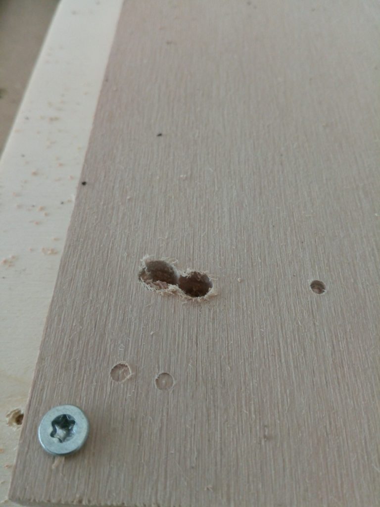
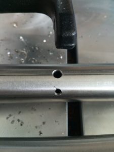
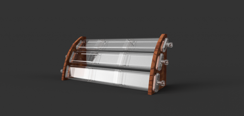
Now everything is assembled again. The tubes are now „perfectly“ straight and parallel. I used a glass plate to verify the alignment.

I did a short test run and I had the same result as before. A nice circular vibration and a not very pretty drill hole. I´m using a diamond cut endmill at the moment and went successfully through two sets of printer frames. I´ve been told in ryans formum (viscious1.com) that diamond cut bits are everything but ideal to dive 12mm into beech plywood. They are very robust so they were the only ones that survived when it came to an error. They are compressing the shavings within the hole and that leads to more and more pressure hence the heat rises and the endmill escapes in the circular movement.

In the past I ordered a endmill from sorotec which broke after some drilling operations. That left me confused what the error might be. I also tried a shorter endmill originally for aluminum which transported the shavings quiete nicely but was too short.

I ordered new endmills again and hopefully all the possible errors caused by the machine are gone and I get my drill patterns and contours out of one endmill.

Wish me luck!


News!

I founded a little company called raise-UAV. The main advantage is the increased time for my projects and that was totally necessary when I look at my roadmap. 🙂

It is primarily focused on the development of open drone systems manufactured with 3D printing technology.

The printer and the mini ghost I´ve started here will be hosted on the company side to keep things easier. Other things not drone and printer related will be posted here on the kleingeist blog in detail. Next bigger projects are a printed and easy to build kajak and an „earth rover“ for research purposes.

There will also be a shop on raise-uav.com where you can buy kits and ready made articles to keep me funded for further development.

I also began a video series picturing the builds and other useful content with its first episode right here

Cheers 🙂

mostly printed camera slider – part 3

Has been tested intensively now. Works ok, with a little practice. I guess I can´t expect more from a printed design due to the weight shift with 500 g class DSLMs. Nevertheless thats enough to do some close slides for products etc.

See it slide here:

There might be some documentation necessary before releasing it on thingiverse as the mechanism needs to be adjusted correctly.