Printed Algae Bioreactor

I thought about building a automated plant care system for some time now. The main purpose was to grow camelia sinensis in a controlled environment, as my three attempts of growing it in a living room or balcony all failed after a year. I was unable to keep the conditions constant enough it seems. I gave up on that, as the grow rate of tea is too low to cover the necessary quantity anyway.

Instead I´m trying to revive my biotechnolgy knowledge and start a printable bioreactor design for cultivating algae. It is not targeted towards a specific species or purpose yet. The first goal is to test the printing process and finding a suitable material with a good transmission and suitable wavelength passthrough. Clear PETG should work as a starting point.

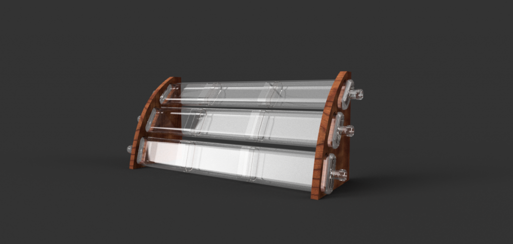
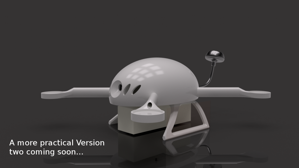
A quick sketch of the concept. The flattube design enhances the surface and therefore the optmum light yield.

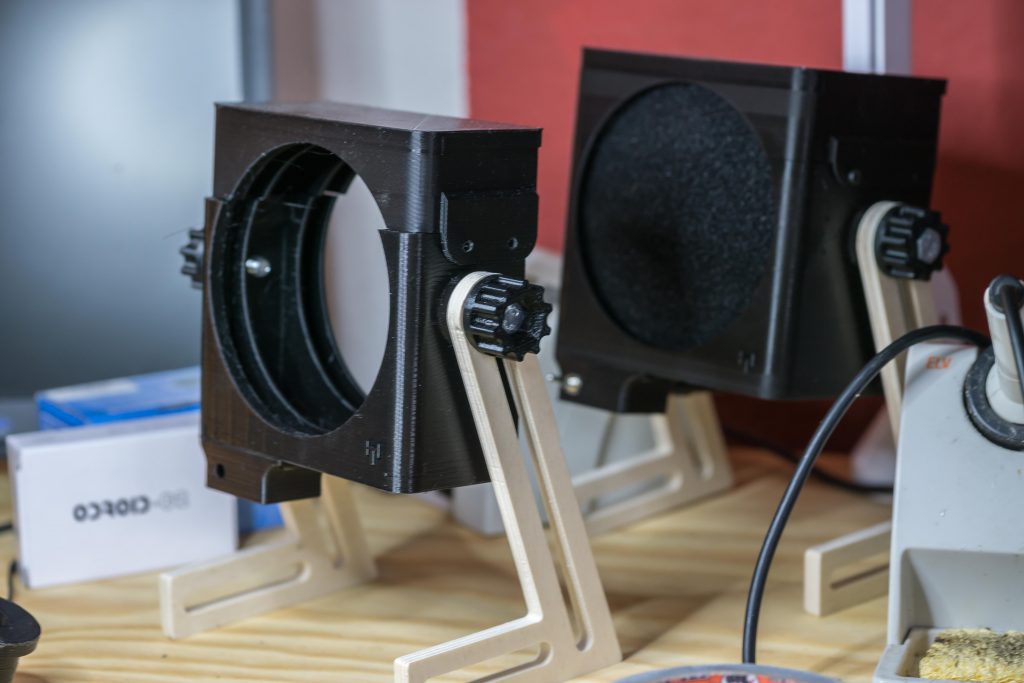
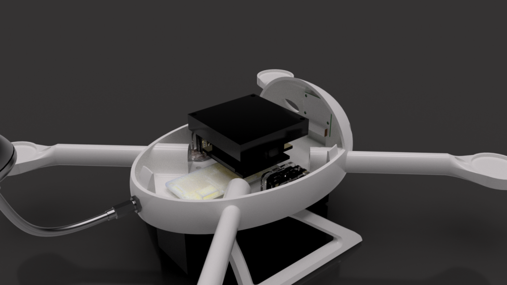
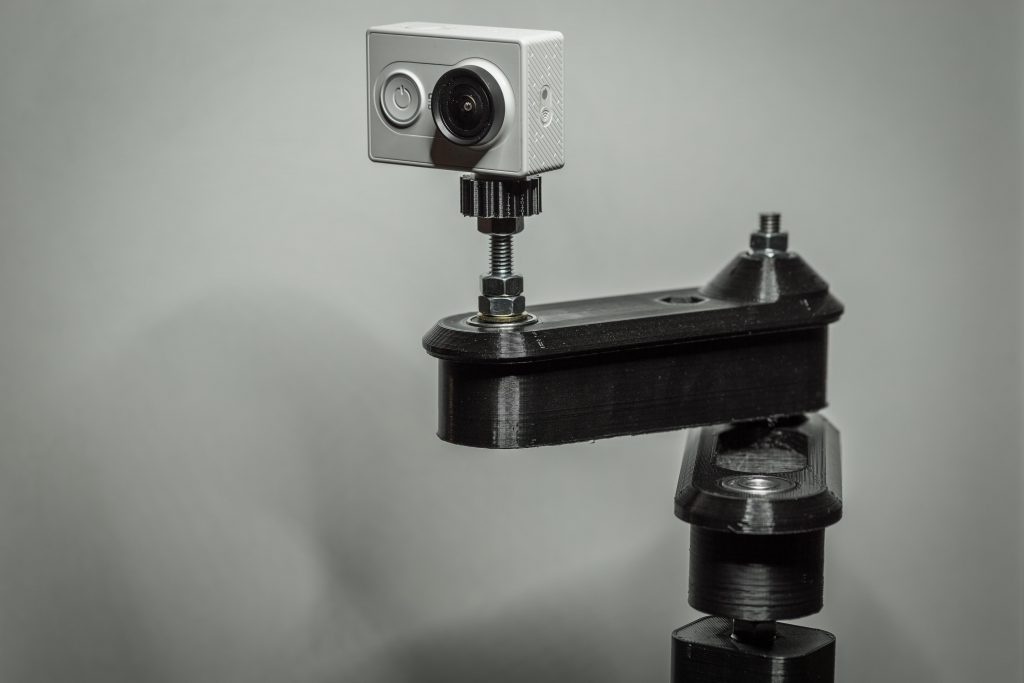
I´m searching for suitable equipment that can be sterilized right now.


Openbuilds C-beam from Ooznest

I had the demand for some more serious aluminum milling. I did that with the MPCNC before and it was kind of okay but I wouldn´t like to mill higher part counts with it. The spindle gets  hot after some time and leads to more flex in the toolhead. It´s not made for aluminum so I looked around for a more suitable platform.

I found the openbuilds C-beam machine to be nicely designed and versatile enough to be worth adding to my machinepark. I looked around for a europe based shop and found openbuilds poland  , v slot europe and ooznest .

I decided to go with the ooznest version as they had the best full kit. I didn´t wanted to source all the parts from here and there. Sometimes it´s nice to have a complete package 🙂

The sipment was fast after the payment went trough and so I had a first look at the package today. All was nicely packed and labeled according to the build section like X, Y and Z Axis. The printed parts for the power supply and the controller board looked pretty nice and felt solid.

Can´t say much yet but a real manual would be more comfortable than a build video. It´s way faster to look at a drawing than to forward, play, stop, rewind, play, the buildvideo 😀

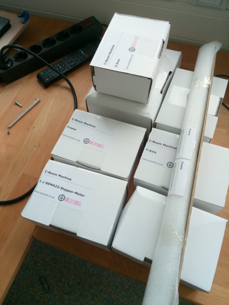
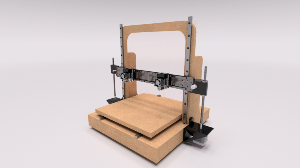
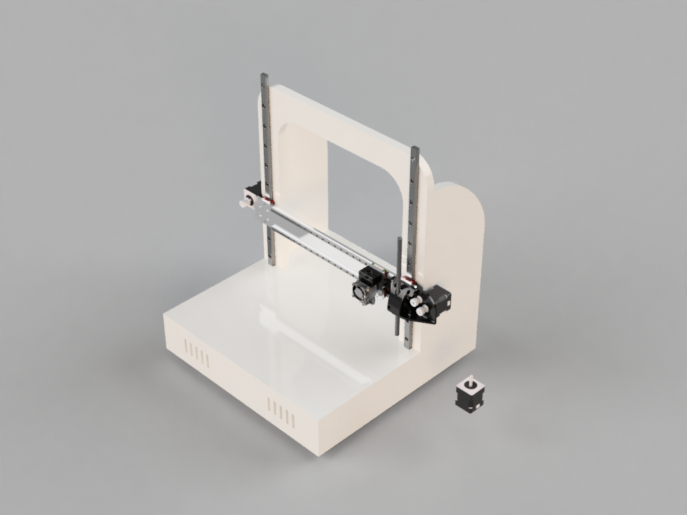
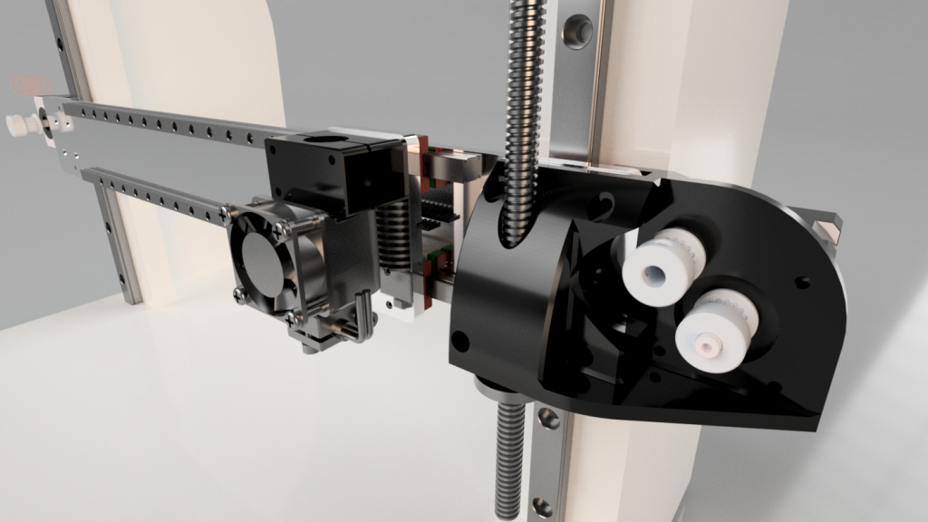
Ready for assembly 🙂

MPCNC- solved drilling issue

Surprise! I had a common chip clearance problem. I considered this as a cause from the beginning and also got some tips from the vicious1..com forum. I milled two complete sets of 3D-printer frames without problems so I couldn´t  believe that this was really the cause.

I drew a test pattern and managed to get it right with an additional ,5mm helical drilling movement. That seems enough for the chips to clear the hole.

I don´t have that much time to get into those issues but the parts didn´t came out perfectly rectangular yet. I tried to manually adjust the stepper position before powering it up but thats still not enough to get the precision I need. I´m using all of the available travel so I´m getting quite a big error in the end.

I need to readjust the frame and the feet as well.

News!

I founded a little company called raise-UAV. The main advantage is the increased time for my projects and that was totally necessary when I look at my roadmap. 🙂

It is primarily focused on the development of open drone systems manufactured with 3D printing technology.

The printer and the mini ghost I´ve started here will be hosted on the company side to keep things easier. Other things not drone and printer related will be posted here on the kleingeist blog in detail. Next bigger projects are a printed and easy to build kajak and an „earth rover“ for research purposes.

There will also be a shop on raise-uav.com where you can buy kits and ready made articles to keep me funded for further development.

I also began a video series picturing the builds and other useful content with its first episode right here

Cheers 🙂

mostly printed camera slider – part 3

Has been tested intensively now. Works ok, with a little practice. I guess I can´t expect more from a printed design due to the weight shift with 500 g class DSLMs. Nevertheless thats enough to do some close slides for products etc.

See it slide here:

There might be some documentation necessary before releasing it on thingiverse as the mechanism needs to be adjusted correctly.

MPCNC – finished dust shoe system

Inspired by one of my readers I had a look  at the dust shoe for the Kress again. I redesigned it completely and got rid of the additional tubes and clamps. I thought that it would be a good idea to have a highly flexible part between vaccum and CNC. If I had ordered the 20mm silicon tubes it may have worked as well but reducing parts is allways priority.

So in the end we got a pretty classic dust shoe here. It doesn´t have a brush at the bottom as it seems to work pretty good at the moment and I really like to see the endmill. However I included three holes at the bottom for a later brush design.

It works pretty good with lighter materials but GFK, aluminum or similar are not fully sucked up.

It has been printed in 0,3mm draft quality for testing purposes.

It has been released on thingiverse here http://www.thingiverse.com/thing:2119491

Now also available in my shop here

Designing and Building a Dual-head 3D Printer

I had the opportunity to try out at least 5 different printers. All of them had sifgnificant backdraws like missing heatbed, price and noise. They all did there job anyway and my Fabrikator is working pretty much „fire and forget“ all the time. Nevertheless I´m tempted to create my own printer just for the sake of adding it to my collection of valuable experiences.

I came up with T-Bot first iteration closely related to prusa´s I3 framewise. I didn´t liked the Z leadscrews standing out that much and too far away from the linear slides so the second version focused on making this a little more aerodynamic.

I am aiming for a precise as possible head and bed positioning mechanics with dual extrusion the bowden way. I have good experience with bowden so I don´t see any significant disadvantages at the moment.

The second version with the new z and x mechanics.

There are E3D V6 mounted on the gantry at the moment but it should be stable enough for light milling operations.

The frame is designed with 16mm MDF in mind but I probably change to a different material (not OSB). Thats why I have to redesign most of the frame parts as the new material is somewhat thinner.

I already have most of the electronic components in mind. The first prototype might be powered by components I have laying around but the finished version is meant to be state of the art 🙂

Watching Thomas Sanladerer´s channel really helped me out making decisions at some points in the design process so thank you for your effort in making great videos, if you ever read this.


mostly printed camera slider – part 2

I took another iteration to make it move like it should. As you can see, in comparison to the previous entry, the case and the mechanics have been modified. The belt system used is a bit more complicated than I initially thought and I couldn´t get it to perform „super smooth“ like its contestants.It is best suited for actioncams as you can see in the picture below. I tried a DSLM and it works somehow but it flexes under the load generating a somewhat unstraight path.

I think it´s okay anyway, taking the money spend into account versus performance. At least it was a good exercise. In the video below are some cam transitions made with it so get the idea of the achievable smoothnes. It´s more like basecap than edelkrone 😛

This project is currently in long term testing and refinement stage.

Raspi based synthesizer with prynth

Some time ago I discovered „The Mitt“ by Ivan Franko. I liked the idea of a flexible software synthesizer combined with a precise hardware controlled parameter modulation.

The idea is to create different concepts of modulation or forms of synthesis in general. The prynth framework itself is based on the legendary „supercollider“ and is served via a webapp running on a rapsberry pi. That way it is very easy to modify with a few clicks.

I had quiete some different synths and other hardware instruments and always came to a point where I really wanted to modify a tiny bit. I know, being limited at some point can help to develop new styles and they teach you how to efficiently use your ressources but this time we have full control over the bits and sounds. FINALLY

I took part in a competition by Ivan in which he gave away a set of prynth pcbs that are used to feed the hardware signals into the raspi. Looks like I´ve won, together with 2 other participiants and for the first time I received a letter from canada!

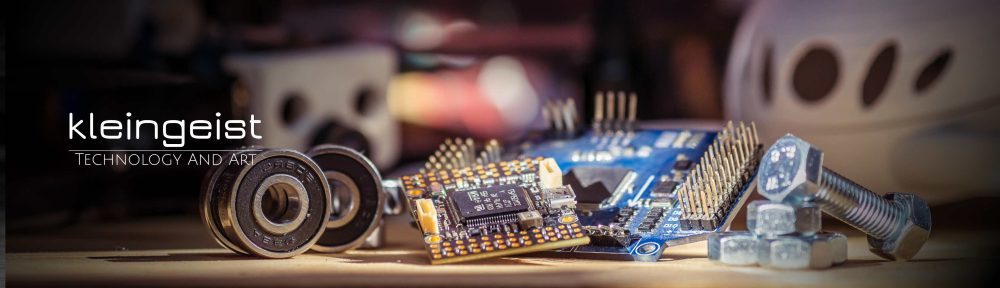
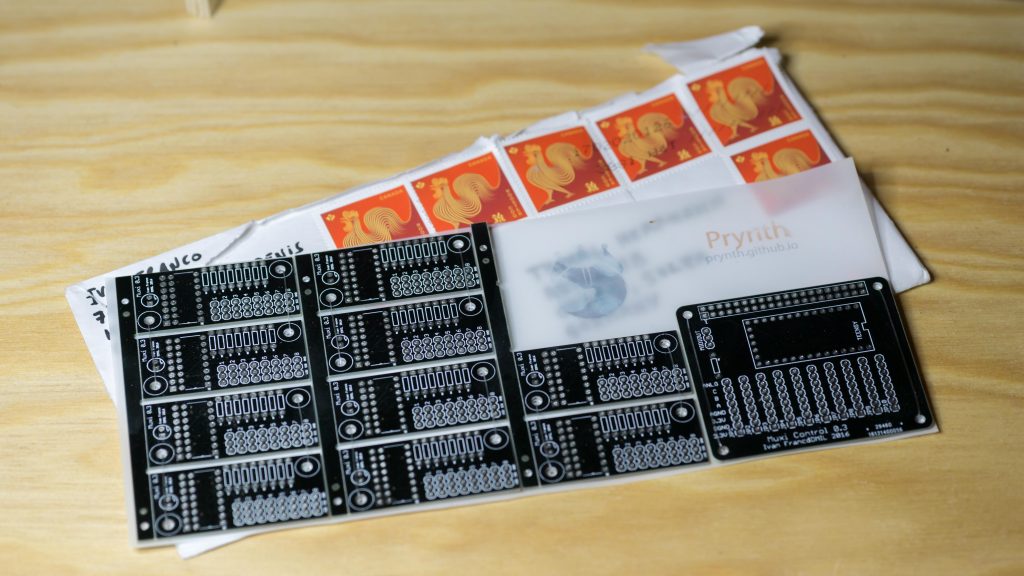
 The main pcb has a teensy on it reading the voltage on the voltage dividers made up by the potentiometers. Up to ten variable resistors are supported by the muxi control mainboard. For bigger projects featuring more control inputs the smaller mux pcbs add a maximum of 80 (!) inputs.

Currently the „hack and make Jena“ group is working on creating a mostly practical synth with some additional features to modulate it fluent and intuitive.

Solder fume extractor

A definetely important tool that I´ve delayed way too long. Micha remembered me of the importance of these devices and as he needed one as well I had even more motivation to finally build one.

It is a simple design with a 24V 180 m³/h fan sucking the air through a 130 x 130 x 10 mm activated charcoal mat. The protoytpe on the pictures was designed with two fans in mind but the single arrangement was sufficient enough. The single fan design also reduced the printing time of course, so I went with that as standard.

I added some legs that increased the range of the system so you don´t have to be too close to the „defumer“. The working range is usually around 40 cm. The closer the better.

Material:

5,6mm female plug – Example

120mm Fan 24 V – Example 

24V power source- Example

Flip switch – Example

Activated charcoal mat – Example